background image

12

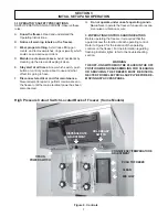
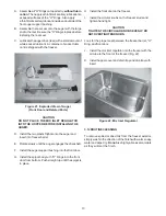
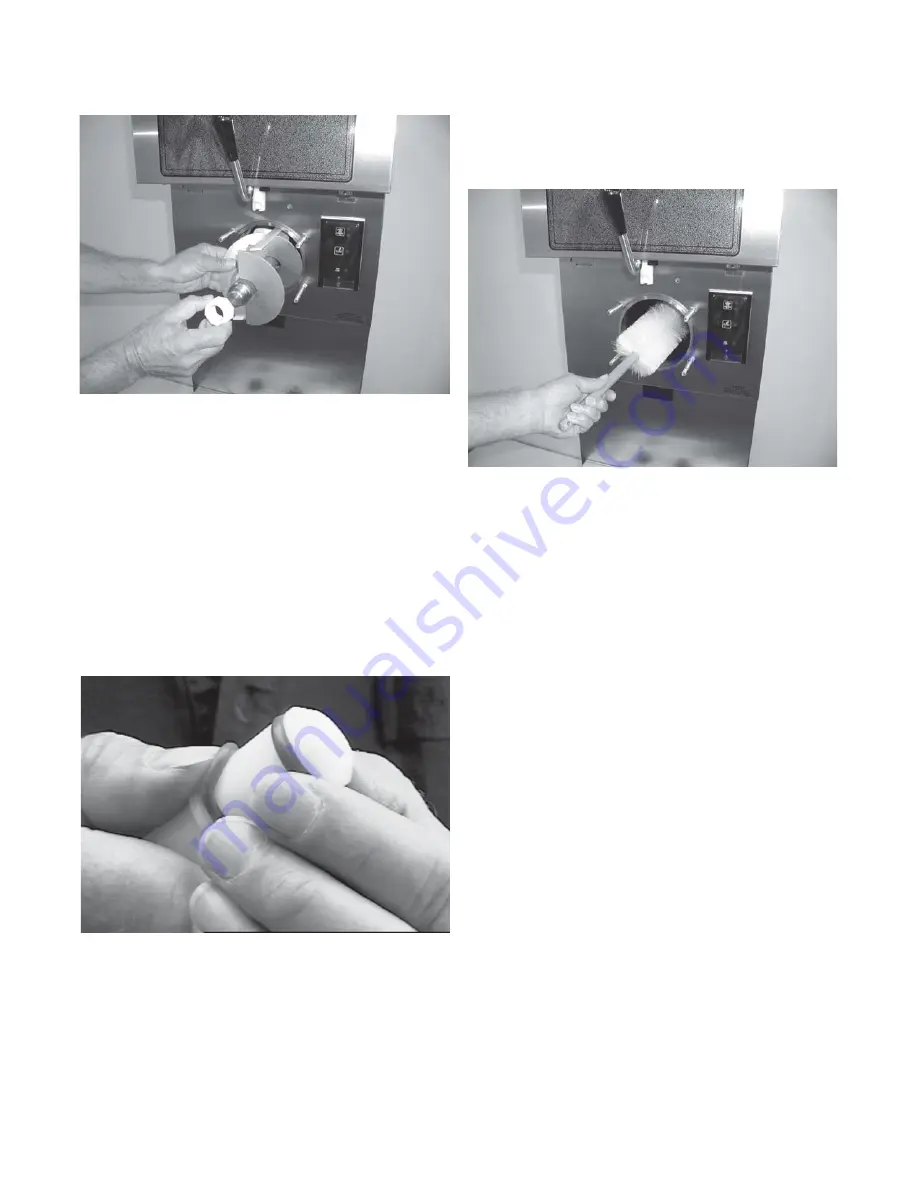
B. Wash the hopper and freezer barrel with warm (120°F)

detergent (Joy or equivalent) water and brushes
provided. (Fig. 20).

C. Clean the drip tray and insert with a detergent (Joy or

equivalent) solution. Rinse with clean hot (135°F)
water.

3.10 SANITIZE FREEZER AND FREEZER PARTS

A. Use a sanitizing solution of 100 parts per million to

sanitize the parts before assembly.

B. Place all parts in the sanitizing solution, then remove

and let air dry.

C. Using this sanitizing solution and the large barrel

brush provided, sanitize the rear of the barrel by
dipping the brush in the sanitizing solution and
brushing.

3.11 ASSEMBLY OF FREEZER

To assemble the freezer parts, refer to the following steps:

NOTE

Petro-Gel sanitary lubricant or equivalent must be
used when lubrication of parts is specified.

NOTE

The United States Department of Agriculture and
the Food and Drug Administration require that lubri-
cants used on food processing equipment be certi-
fied for this use. Use lubricants only in accordance
with the manufacturer's instructions.

Figure 20.  Cleaning Freezer Barrel

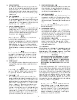
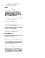
E. Remove the auger assembly from the freezer (Fig.18).

Keep the rear of the auger shaft tipped up once it is
clear of the freezer to avoid dropping rear seal.

Figure 18.  Auger Shaft Removal

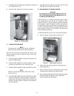
Figure 19.  Removing "O" Ring

F. Remove scaper blades and the rear seal assembly.

G. Wipe socket lubricant from the drive end (rear) of the

auger with a cloth or paper towel.

H. Remove all "O" Rings from parts by first wiping off the

lubricant using a clean paper towel. Then squeeze the
"O" Ring upward with a dry cloth (Fig. 19). When a loop
is formed, roll out of the "O" Ring groove.

WARNING

DO NOT USE ANY TYPE OF SHARP OBJECT TO
REMOVE THE "O" RINGS.

3.9 CLEANING THE FREEZER PARTS

Place all loose parts in a pan or container and take to the
wash sink for cleaning. To clean freezer parts refer to the
following steps:

A. Place all parts in warm (120°F) mild detergent (Joy or

equivalent) water and clean with brushes provided.
Rinse all parts with clean hot (135°F) water.

CAUTION

DO NOT DAMAGE PARTS BY DROPPING OR
ROUGH HANDLING.

Summary of Contents for OPTIMA 212

Page 1: ...OPTIMA 212 OWNER S MANUAL Manual No 513589 Jan 2002 Rev 1...

Page 2: ......

Page 3: ...are certified in the Stoelting Technicare program Model No _______________________ Serial No _______________________ Purchase Date ____________________ Start Up Date ____________________ CALL Distrib...

Page 4: ......

Page 5: ...Freeze Down and Operation 9 3 5 MixInformation 10 3 6 Removing Mix From Freezer 10 3 7 Cleaning The Freezer 11 3 8 Disassembly of Freezer Parts 11 3 9 Cleaning The Freezer Parts 12 3 10 Sanitize Free...

Page 6: ...4 7 InstallingTrayandCover 4 8 PowerCordConnection 5 9 Controls 7 10 Mix Inlet Regulator 9 11 CleanControl 9 12 SanitizingHopper 9 13 DrainingSolution 9 14 DispensingProduct 10 15 RemovingMixInletReg...

Page 7: ...ls to provide a uniform product The freezer is designed to operate with almost any type of commercial shake mix available This manual is designed to assist qualified ser vice personnel and operators i...

Page 8: ...scription Optima 212 38 Voltage AC 1 PH 208 230 Total Run Amps 10 5 Drive Motor 3 4 HP Compressor 10 760 BTUH 90 F 0 F Use 20 amp HACR circuit breaker Automatic safeguard circuit built into electronic...

Page 9: ...n a safe working environment Thelabelshavebeendesignedtowithstand washing and cleaning All labels must remain legible for the life of the freezer Labels should be checked periodi cally to be sure they...

Page 10: ...overrun Place a spirit level on top of the freezer at each corner to check for level condition If adjustment is necessary level the freezer by turning the caster in or out and tighten the locknut Fig...

Page 11: ...OF ELECTRICAL SUPPLY BEFORE SERVICING A Remove the left side panel and electrical box cover B Disconnect the wires from the terminal block Disconnect the green ground wire from the grounding stud Fig...

Page 12: ...6...

Page 13: ...e main electrical power has been disconnected G Do not operate under unsafe operating condi tions Never operate the freezer if unusual or exces sive noise or vibration occurs 3 2OPERATINGCONTROLSANDIN...

Page 14: ...a minimum of 10 minutes Then turn to off wait 5 seconds and turn on F DRIVEMOTOROVERLOAD TheinternalDRIVEMOTOROVERLOADwilltripifthe drive motor is overloaded It will reset after approxi mately 10 12 m...

Page 15: ...on 3 8 liters of mix into the hopper Allow the mix to flush out about 8 ounces 0 23 liters of sanitizing solution and liquid mix Close the spigot D Fill hopper with approximately 5 gallons 19 liters o...

Page 16: ...Remove the mix inlet regulator from the hopper by pulling straight up Fig 15 B Place the OFF ON rocker switch in the ON position andpushtheCLEANswitchtorotatetheauger Allow the mix to agitate in freez...

Page 17: ...ger C Allowthewatertoagitateforapproximately5minutes NOTE If freezer is left in CLEAN for more than 30 minutes it will go to error D Openthespigottodrainthewater Remembertoplace a bucket or container...

Page 18: ...ent be certi fied for this use Use lubricants only in accordance with the manufacturer s instructions Figure 20 Cleaning Freezer Barrel E Removetheaugerassemblyfromthefreezer Fig 18 Keep the rear of t...

Page 19: ...t F Install the auger support bushing into the front door G Install the spigot body with O Rings into the front door from bottom Push straight up until the spigot is in place H Install the front door...

Page 20: ...n a deliming solution for an extended period of time more about delimers in Additional Information It is recommended that a maintenance schedule be fol lowed to keep the freezer clean and operating pr...

Page 21: ...ose cleaners do not have the ability to remove milkstone Milkstone will become a problem if not remedied with additional products and procedures THE USE OF CHLORINE TEST STRIPS Test strips are used to...

Page 22: ...proper tension Push belt in with one finger belt should deflect about 3 8 2 Lubricate condenser fan motor with S A E 20 weight oil Three to six drops is required CAUTION DO NOT OVER LUBRICATE RESULTI...

Page 23: ...n o i t a r e g i r f e R 5 e c i v r e s r o f r o t u b i r t s i d l l a C t s u j d a e R 1 e c i v r e s r o f r o t u b i r t s i d l l a C 2 e c i v r e s r o f r o t u b i r t s i d l l a C 3...

Page 24: ...n i r O r o t a l u g e r t e l n i x i M 2 e b u t r i a r o t a l u g e r t e l n i x i M 3 d e k c o l b n w o d k a e r b t c u d o r P 4 r o t a l u g e r t e l n i x i m e c a l p e R 1 g n i r...

Page 25: ...0 2 0 3 0 4 0 5 0 6 0 7 0 R R E R R E R R E R R E R R E R R E R R E NOTE SENSOR IS 10 000 OHMS AT 77 To Clear Error Modes Clean Error 04 Allow freezer to remain on light blinking with the power switc...

Page 26: ...7 t r a u Q 8 Y T I C A P A C G N I Z E E R F F 0 8 0 7 r u o h r e p s n o l l a G 0 2 6 1 C 7 6 2 1 1 2 r u o h r e p r e t i L 1 9 3 7 s n o i t i d n o c g n i t a r e p o r e p o r P S G N I T T...

Page 27: ...NG PN QTY DESCRIPTION 1 336530 SV 1 Front Door Shake 2 625314 1 Ring O 6 OD x 1 4 CS 3 1 Door Pin 4 3177738 1 Spigot Body 5 624614 2 Ring O 3 4 IDX 1 0 ODX 1 8 CS 6 508135 001 Lubricant Petro Gel 4 Oz...

Page 28: ...TION 1 4177749 1 Auger Shaft 2 666786 1 Seal Rear with Insert 3 624678 1 Ring O 1 1 2 x 1 1 8 x 3 16 CS 4 149002 1 Bearing Front Auger Celcon 5 508048 001 Lubricant Fel Pro 51171 6 508135 001 Lubrican...

Page 29: ...23...

Page 30: ...24...

Page 31: ...25...

Page 32: ...26 DS SV ASSY...

Page 33: ...27 A C...

Page 34: ...28...

Page 35: ...pper Evaporator Assembly 3 231105 1 Capillary Tube 072 x 026 20 4 762443 1 Valve Expansion 1 Ton 5 458003 1 Indicator Sight Glass 1 4 6 342004 1 Drier 7 284083 1 Condenser 8 282032 1 1 PH Compressor 9...

Page 36: ...30...

Page 37: ...31...

Page 38: ...32 SV DS ASSY...

Page 39: ...33...

Page 40: ...34...

Page 41: ...Valve Expansion 1 Ton 5 458003 1 Indicator Sight Glass 1 4 6 342004 1 Drier 7 284068 1 Condenser 8 282032 1 1 PH Compressor 9 342020 1 Drier 10 282033 1 3 PH Compressor 11 2171962 1 Sensor Assembly 12...

Page 42: ...36...
Page 43: ...es are subject to the conditions that Buyer a signs and returns to Stoelting upon installation the Checklist Warranty Registration Card for the affected equipment b gives Stoelting prompt written noti...

Reviews: