background image

37

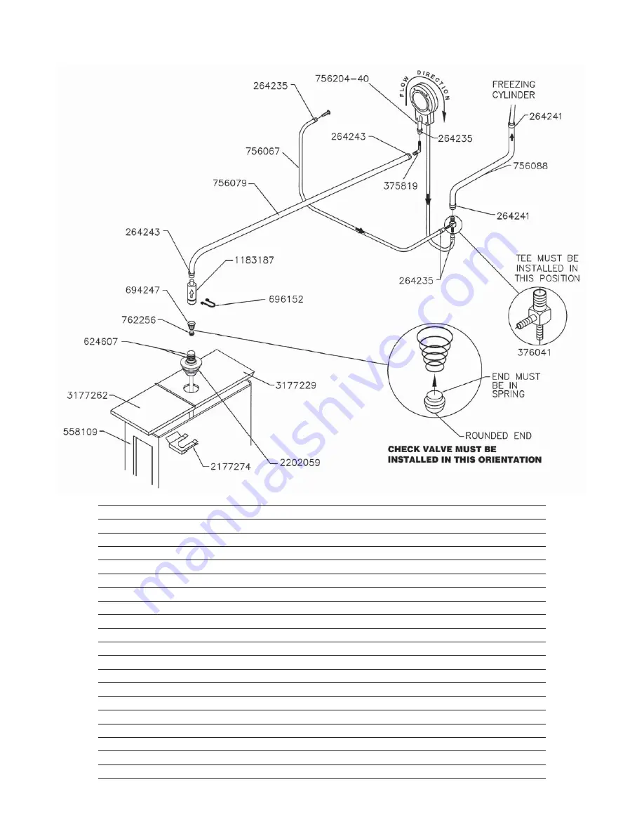
 Part 

Number 

Description 

Quantity


264235 

Clamp - Metal (1/4” ID Tubing) (Cab) 

8


264241 

Clamp - Metal (1/2” ID Tubing) (Cab) 

4


264243 

Clamp - Metal (3/8” ID Tubing) (Cab) 

8


375819 

Elbow - Barbed (3/8”- 1/4”) (Cab) 

2


376041 

Tee Connector - 3-Way (Stainless) (Cab) 

2


558109 

Mix Container Only (Cab) 

2


624607 

O-Ring - Check Valve Body - Black (Cab) 

4


694247 

Spring - Cone (Spigot Cam) (Soft Serve) & (Cab Check Valve) 

2


696152 

Clip - Lock (Check Valve) (Cab) 

6


756067 

Tubing - 1/4” ID - Clear - Air Line (25’ Increments) (Per Inch) 

Two 13”


756079 

Tubing - 3/8” ID - Clear - Mix Line (25’ Increments) (Per Inch) 

Two 24”


756088 

Tubing - 1/2” ID - Clear - Mix Line (25’ Increments) (Per Inch) 

Two 6”


756204 

Tubing - 1/4” ID - Pump (50’ Box Only) (Per Inch) (Cab) 

-


756204-40 

Tubing - 1/4” ID - Pump (Pre-Cut 40” Piece) (Cab) 

8


762256 

Check Valve - Mix Outlet (Cab) 

2


1183187 

Check Valve - Mix In Line (Outer) (Cab) 

2


2177274 

Clip - Retaining (Mix Probe To Cover) (Cab) 

2


2187307 

Pick-Up Tube - Mix (Cab) 

2


3177229 

Cover - Rear (Mix Container) (Cab) 

2


3177262 

Cover - Front (Mix Container) (Cab) 

2

6.5 CAB 

TUBING

Summary of Contents for SU444 Air Cooled

Page 1: ...Model SU444 OPERATORS MANUAL Manual No 513639 Rev 3 ...

Page 2: ......

Page 3: ...s built prior to date of change DO NOT ATTEMPT to operate the machine until instructions and safety precautions in this manual are read completely and are thoroughly understood If problems develop or questions arise in connection with installation operation or servicing of the machine contact Stoelting Stoelting Foodservice Equipment 502 Highway 67 Kiel WI 53042 1600 U S A Main Tel 800 558 5807 Fa...

Page 4: ...pecific safety information the following safety defini tions are provided to assist the reader The purpose of safety symbols is to attract your at tention to possible dangers The safety symbols and their explanations deserve your careful attention and understanding The safety warnings do not by themselves eliminate any danger The instructions or warnings they give are not substitutes for proper ac...

Page 5: ...Information Regarding Cleaning and Sanitizing 9 3 4 Disassembly of Left Side 10 A Remove Front Door and Auger 11 3 5 Disassembly of Right Side 11 A Remove Blender SU444 Only 11 B Remove Front Door and Auger 11 3 6 Cleaning Disassembled Parts 12 3 7 Sanitizing Parts 12 3 8 Cleaning the Machine 12 3 9 Assembling the Left Side 12 3 10 Assembling the Right Side 13 3 11 Sanitizing 14 3 12 Initial Freez...

Page 6: ...ight Side 21 4 9 Overrun Adjustment 22 4 10 Mix Pump Hose Reposition 23 4 11 Mix Pump Hose Replacement 24 4 12 Cab Temperature Adjustment 24 4 13 Drive Belt Tension Adjustment 25 4 14 Condenser Cleaning Air Cooled Machines 25 4 15 Preventative Maintenance 25 4 16 Extended Storage 26 5 Troubleshooting 5 1 Error Codes Right Side 27 5 2 Troubleshooting Error Codes Right Side 27 5 3 Troubleshooting Ma...

Page 7: ...d to dispense soft serve product from the left side and shake product from the right side The SU444 has a blender attached to the front door of the shake side This manual is designed to assist qualified service per sonnel and operators with installation operation and maintenance of the SU444 and U444A SECTION 1 DESCRIPTION AND SPECIFICATIONS Figure 1 2 Dimensions Figure 1 1 Model SU444 Machine ...

Page 8: ...um overcurrent protection device 50A 40A 30A 25A 50A 40A 30A 25A Compressor Soft Serve 19 000 Btu hr Scroll Compressor R 404A Shake 15 000 Btu hr Scroll Compressor R 404A Cabinet 1 300 Btu hr Compressor R 134a Drive Motor Soft Serve 2 hp Shake 3 4 hp Cooling Water cooled units require 1 2 N P T water and drain fittings Maximum water pressure of 130 psi Minimum water flow rate of 3 GPM Ideal EWT of...

Page 9: ...tion may cause personal injury severe damage to the machine and will void fac tory warranty Installation of the machine involves moving the machine close to its permanent location removing all crating set ting in place assembling parts and cleaning A Uncrate the machine B Install the four casters Turn the threaded end into the machine until no threads are showing To level turnoutcastersnomorethan1...

Page 10: ...heild in place move the spigot handle to the right WARNING Hazardous Moving Parts Blender shaft and agitator can grab and cause injury Do not operate blender without protective shield or swing splash shield C The blender should rotate clockwise looking from the top of the blender D If the rotation is counterclockwise refer to the wiring diagram located behind the header panel and check the diode d...

Page 11: ...e connected to the standard mix container or up to three prepacked mix bags Follow the instructions below that match your configuration Standard Connection 1 Place the mix pickup assembly through the hole in the cover and install the retaining clip 2 Connect a 24 61cm length of 3 8 9 5mm ID plastic food grade tubing to the mix pickup assembly Secure with a hose clamp 3 Connect the elbow fitting to...

Page 12: ... 9 5mm ID plasticfoodgradetubing toabagadapter Secure with hose clamps 2 Slide the hose clip over the free end of the tubing Attach the free end of the tubing to a manifold adapter Securewithalargehose clamp 3 Push the manifold adapter with spring and valve into the left port nearest the manifold outlet of the mix inlet manifold and secure with retaining clip See Figure 2 4 4 If using two mix bags...

Page 13: ... is required that the op erator know the function of each operating control Refer to Figure 3 1 for the location of the operating controls on the machine For the information regarding error codes displayedonthecontrolpanel refertothetroubleshooting section of this manual A PUMP SWITCH BOTH SIDES The pump motor switch is the toggle switch located under the header panel When the switch is placed in ...

Page 14: ...ing cylinder can then be controlled with the Freezing Cylinder OFF ON switch K FREEZING CYLINDER OFF ON SWITCH RIGHT SIDE The Freezing Cylinder OFF ON switch is a two position toggle switch used to supply power to the right freezing cylinder control circuit When the switch is in the OFF position the freezing cylinder s refrigeration system and auger will not operate When the switch is in the ON po...

Page 15: ...uip ment and utensils that are exposed to dairy products Thesefilmswillaccumulateslowlyonsurfacesbecauseof ineffective cleaning use of hard water or both Milkstone is usually a porous deposit which will harbor microbial contaminants and eventually defy sanitizing efforts Once milkstone has formed it is very difficult to remove Without using the correct product and procedure it is nearly impossible...

Page 16: ...oduct To disassemble the left side refer to the following steps PROPER DAILY MAINTENANCE The Only Way toAssure Food Safety and Product Quality Proper daily maintenance can involve a wide variety of products and procedures Overall the products and procedures fall into three separate categories Please note that this is a brief overview intended for informational purposes only 1 CLEANING This involve...

Page 17: ...ve the door by pulling it off the studs A REMOVE FRONT DOOR AND AUGER 1 Make sure the Clean Off Serve switch is in the OFF position 2 Remove the knobs on the front door and remove the door by pulling it off the studs 3 Remove the air bleed valve by unscrewing the knob while holding the valve stem from behind Remove the compression spring and push the air bleed valve through the rear of the front d...

Page 18: ...tize all machine parts following procedures outlined below 3 7 SANITIZING PARTS A Useasanitizer mixedaccordingtomanufacturer s instructions to provide a 100 parts per million strength solution Mix sanitizer in quantities of no less than 2 gallons of 90 to 110 F 32 C to 43 C water Any sanitizer must be used only in accordance with the manufacturer s instructions B Place all parts in the sanitizing ...

Page 19: ...not overtighten Proper o ring seal can be observed through the transparent front door 3 10 ASSEMBLING THE RIGHT SIDE Refer to the following steps for assembling the right freezing cylinder NOTICE Petrol Gel sanitary lubricant or equivalent must be used when lubrication of machine parts is specified NOTICE The United States Department of Agriculture and the Food and Drug Administration require that...

Page 20: ...x pump switch in the ON position and open air bleed valve on the front door by pushing valve in and holding C Let sanitizing solution fill the machine barrel to air bleed valve then close the valve by pulling out to lock in place D Place the CLEAN OFF SERVE toggle switch in the CLEAN position E Check for leaks when the machine barrel is first pressurized with sanitizing solution 1 Check for leaks ...

Page 21: ... button once The display will read CutOut amps 11 Press the SET button A cursor will start blinking under the far right digit 12 Change the value to 8 0 Press the left arrow button to move the cursor Press the up arrow Ý button to increase the digit When a digit reaches 9 pressing the up arrow button again will change the value to 0 13 After entering 8 0 press SET to save this value The LCD will r...

Page 22: ... Place the mix pump switch in the ON position F Place a container under the spigot and open it to allow the mix to flush out about 8 ounces 0 23 liters of sanitizing solution and liquid mix Close the spigot G Open the air bleed valve on the front door by pressing and holding Hold the valve open until the mix level in the freezing cylinder is 1 2 from the air bleed valve H Place the Clean Off Serve...

Page 23: ...tains one continuous mix pump hose When looking at the face of the peristaltic mix pump the left side of the hose is the mix intake or pickup The right sideofthehoseisthemixdischarge Mixisdrawn up the pickup side of the hose and transferred through the discharge side to the machine Fig 3 6 B Air Operation The air compressor operates whenever the peristaltic mix pump is running Air enters through a...

Page 24: ...ed when disassembling or servicing CAUTION System Under Pressure Never disconnect hoses from the machine or the pump without first opening the spigot to relieve pressure A Loosen the clamp and remove the air hose from the pump compressor B Loosen the clamp and disconnect the mix pump hose Remove the pickup hose and the mix pickup assembly from the mix container C Completely disassemble the hose as...

Page 25: ... consistency setting is displayed The higher the number the firmer the product consistency The SECTION 4 MAINTENANCE AND ADJUSTMENTS controlmaybesetfrom1to9 Thevalueincreases by 1 each time the up arrow button is pressed After the value reaches 9 numbering restarts at 0 The 0 setting cannot be set D Press the SET button once to save the setting and return to the current mode display 4 4 LOCKING TH...

Page 26: ...ttings as needed I When all changes have been completed press the up arrow button from ExitMenu to return to the current mode display 4 6 READINGS SERVICE PERSONNEL ONLY RIGHT SIDE The IntelliTec control continuously monitors and records temperatures voltages amps and error code details Each reading is beneficial to service personnel when troubleshooting DISPLAY READINGS Following are the readings...

Page 27: ...ollowing adjustments directly affect product consis tency and length of time in Serve Mode The default settings have been created using a 5 milkfat soft serve mix and provide optimal product consistency while pro longing product life CutOut amps It is recommended to set the CutOut value at initial startup and when changing mix types Adjustments to this setting directly affect the lengthofthefreezi...

Page 28: ...e affects the amount of time between freezing cycles during Serve Mode Refriger This setting changes how the control handles the storagerefrigerationcycle Thecorrectsettingfor the SU444 and U444A is Cabinet CabCutIn F If the Refriger value is set to Cabinet this setting determines the temperature at which the refrigeration cycle starts If None 1 Hopper or 2 Hopper is selected for the Refriger sett...

Page 29: ...rrun F Tighten the allen screw then place the wrench back in its clip Replace the lower back panel and secure with the four screws Turn the mix pump power switch to the ON position 4 10 MIX PUMP HOSE REPOSITION Mix pump hose must be repositioned every 800 gallons of mix pumped or every 2 weeks Failure to reposition the hose will result in reduced mix pump liquid capacity dispensestoppage popping a...

Page 30: ...esulting in pump damage P Connect the free end of the mix pump hose to the 3 way Tee When all connections are complete the 3 wayTee must be lower than the black pump housing Q The pump is now ready to sanitize 4 12 CAB TEMPERATURE ADJUSTMENT Cab temperature is monitored and controlled by two set tings on the IntelliTec control CabCutIn and CabCtOut The cut in value determines the temperature at wh...

Page 31: ...condenser D If the condenser is dirty place a wet towel over the condenser E Using compressed air or a CO2 tank blow out the dirt from the inside of the condenser Most of the dirt will cling to the wet towel NOTE If the condenser is not kept clean refrigeration ef ficiency will be lost 4 15 PREVENTATIVE MAINTENANCE It is recommended that a preventative maintenance schedule be followed to keep the ...

Page 32: ...auger flights in a plastic bag with a moist paper towel This will prevent the flights from becoming brittle if exposed to dry air over an extended period over 30 days D Forwater cooledmachinesthatareleftinunheated buildings orbuildingssubjecttofreezing thewater must be shut off and disconnected Disconnect the water inlet fitting The fitting is located at the rear of the machine Run the compressor ...

Page 33: ...n Sleep 2 Mode This error is generally caused by very low mix levels in the machine s mix container or from product breakdown Another common cause results from a restriction preventing mix from entering the freezing cylinder Check the mix in the cabinet If the level mix is low add mix If there is a possibility that the mix has broken down clean and sanitize the machine and replace the mix with fre...

Page 34: ...f the error persists contact your Authorized Stoelting Distributor for further assistance Error Code 9 High Pressure Cutout High Pressure Cutout Errors E9 are usually caused by a dirty or inefficient condenser In air cooled condenser models check for proper air clearance around the machine In water cooled condenser models check for proper water flow If the error persists contact your Authorized St...

Page 35: ...Fill with fresh product 4 Left side Standby Serve switch in the Standby position 4 Place the Standby Serve switch in the Serve position Freeze up Product will not dispense easily 1 Right side CutOut setting is too high 1 Adjust CutOut setting to match product requirements See Section 3 12 2 Left side temperature setting is too low 2 Adjust the temperature See Section 4 2 3 Low overrun setting 3 In...

Page 36: ...2 Compressor makes loud noise 1 Reversed scroll rotation 1 Change wiring Fan motor doesn t operate or high head pressure 1 Left side not connected to power supply 1 Make sure the left side is connected to a power supply 2 Low line voltage 2 If line voltage is less than 215V then the fan motor needs to be rewired See Section 2 4 Not cooling at startup 1 Reversed scroll rotation 1 Check compressor f...

Page 37: ...ff Draw 2 3 pints to reduce system pressure to zero Turn pump on Purge remaining air in mix bag and pick up hose Important before connecting the pick up hose to the mix bag remove as much air from the mix bag as possible 1 Out of Mix 1 Replenish mix supply 2 Mix pump hose kinked inside black cover clamp 2 Disconnect pump from power source Remove four cover clamp thumb screws Separate cover clamp h...

Page 38: ...mmediately disassemble and clean pump 1 Mix pump hose service life is exceeded 1 Remove mix pump hose Disconnect pump from power source Remove mix pump cover clamp Clean the rollers a small amount of soapy water Clean mix from pump See Section 4 2 for hose replacement Pump is noisy squeaking Note The action of the air compressor rocking arm creates a repetitive clicking sound during operation This...

Page 39: ...324509 Decal Cleaning Instructions 1 324548 Decal Adequate Ventilation 6 1 324565 Decal Temperature Adjustment 1 324566 Decal Wired According To 1 324594 Decal Attention Heat Sensitive 1 324686 Decal Danger Automatic Start 2 324728 Decal Contactor Identification 1 324796 Decal Freezing 1 324797 Decal Standby Serve 1 324798 Decal Clean Off Serve Switch 1 324799 Decal Pump Off On 2 324801 Decal Mix ...

Page 40: ...g Spigot Black 2 624678 O Ring Rear Seal Black 1 625133 O Ring Front Door Black 1 667868 Seal Rear Auger Orange 1 694200 Spring Air Bleed Valve 1 694255 Spring Auger Flight 6 1151859 Adapter Rear Seal Code 1 1 2104552 Support Front Auger 1 2183106 Valve Air Bleed 1 2187680 Spigot Body 1 2187696 Front Door 1 4151178 Auger Shaft 1 694200 2187680 2187696 624520 625133 2183106 149003 694255 381804 415...

Page 41: ...ront Door Black 1 667868 Seal Rear Auger Orange 1 694200 Spring Air Bleed Valve 1 2183106 Valve Air Bleed 1 2183751 Scraper Blade 3 2187877 Bushing Front Auger Support 1 2187880 Adapter Rear Seal 1 2187878 Spigot Body 1 2187941 Auger Shaft 1 6 3 RIGHT SIDE SHAKE AUGER SHAFT AND FRONT DOOR PARTS 482019 482004 694200 624614 2187878 2187877 625314 2187941 2183751 2187880 667868 336548 SV 624520 21831...

Page 42: ...lar 1 417010 Grid Drip Tray Metal 1 521026 Blender Agitator 1 674183 Blender Shaft 1 681518 Swing Shield Plastic 1 744262 Tray Drain Shake 1 744276 Tray Drain Soft Serve 1 744287 Tray Drip 1 6 4 BLENDER PARTS AND DRIP TRAY 274031 674183 521026 681514 744287 417010 ...

Page 43: ... Lock Check Valve Cab 6 756067 Tubing 1 4 ID Clear Air Line 25 Increments Per Inch Two 13 756079 Tubing 3 8 ID Clear Mix Line 25 Increments Per Inch Two 24 756088 Tubing 1 2 ID Clear Mix Line 25 Increments Per Inch Two 6 756204 Tubing 1 4 ID Pump 50 Box Only Per Inch Cab 756204 40 Tubing 1 4 ID Pump Pre Cut 40 Piece Cab 8 762256 Check Valve Mix Outlet Cab 2 1183187 Check Valve Mix In Line Outer Ca...

Page 44: ......

Page 45: ...obligations remedies are subject to the conditions that Buyer a signs and returns to Stoelting upon installation the Checklist Warranty Registration Card for the affected equipment b gives Stoelting prompt written notice of any claimed breach of warranty within the applicable warranty period and c delivers the affected equipment to Stoelting or its designated service location in its original packa...

Reviews: