26
Installation
Air/Flue gas system
,QVWDOODWLRQRIKRUL]RQWDOÀXHWHUPLQDOV
Before installing the terminal
%HIRUHDVVHPEOLQJWKHÀXHWHUPLQDO
LWLV¿UVWQHFHVVDU\WRSHUIRUPWKHIRO
-
ORZLQJRSHUDWLRQV
t
&KHFNWKHÀXHWHUPLQDOIRUSRVVL
-
ble damage.
t
Determine the proposed location
RIWKHÀXHWHUPLQDO
t
Drill a hole through the wall of a
max. of 10mm wider then the air
VXSSO\SLSHIRUWKHÀXHWHUPLQDO
t
+RUL]RQWDO ÀXH WHUPLQDO ZLWK ÀH
-
xible exterior gaskets can be in-
stalled inside out, in which case
the drilled hole must be 25mm
wider then the diameter of the air
supply pipe.
Take due care to protect the applian-
ce from dust and grit during drilling
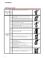
,QVWDOOLQJWKHÀXHWHUPLQDO
Determine the thickness of the wall
and cut i necessary the wall terminal
to the corrisponding length.
Remove the burs.
$WWHQWLRQ
The length is correct if the outer wall
SODWHRUURVHWWHDUHÀXVKZLWKWKHRW
-
side wall.
Part list:
+RUL]RQWDOÀXHWHUPLQDO
2. Wall plate or rosette
3. Concentric bend
4. Locking bend (optional)
5. Flue pipe
6. Air inlet pipe
7. Twin pipe connection.
,QVHUWWKHÀXHWHUPLQDOLQWRWKHGULOOHG
KROH7KHDLUVXSSO\SLSHIRUWKHÀXH
terminal must either be installed le-
vel or tilted slightly downwards to the
outside (max. 10mm per meter).
To prevent rainwater from penetrating
WKHV\VWHPHQVXUHWKDWWKHÀHWHUPL
-
nal is never installed up side down.
Close the gap between the air intake
pipe and rhe hole in the wall with wa-
ter resistant sealant.
,QVWDOO WKH URVHWWHV RU ZDOO SODWHV
DURXQG WKH ÀXH WHUPLQDO DQG DWWDFK
with screws or kit.
&RQQHFWLQJWKHÀXH
Connect the appliance to the terminal.
Start at the outlet of the appliance.
Use only water for greasing the seals.
Important
,QVWDOOSURGXFWVDFFRUGLQJWR1DWLR
-
nal Regulations.
Cleaning is possible with a wet towel
or with some detergent.
4
3
2
1
7
6
5


