9
GB
Operating principle
This is a fully modulating boiler.
The control unit of the boiler adapts
the modulation ratio automatically to
the heat demand requested by the
system. This is done by controlling
the speed of the fan.
As a result, the Whirlwind mixing
system will adapt the gas ratio to the
chosen fan speed, in order to maintain
WKHEHVWSRVVLEOHFRPEXVWLRQ¿JXUHV
DQG WKHUHZLWK WKH EHVW HI¿FLHQF\
7KH ÀXH JDVHV FUHDWHG E\ WKH
combustion
are
transported
downwards through the heat exchan-
ger and leave the boiler at the
top into the chimney connection.
The return water from the system
enters the boiler in the lower section,
ZKHUHLVWKHORZHVWÀXHJDVWHPSH
-
UDWXUH LQ WKH ERLOHU ,Q WKLV VHFWLRQ
condensation
takes
place.
The
water
is
being
transpor-
ted upwards through the heat
exchanger, in order to leave the
ERLOHU DW WKH ÀRZ FRQQHFWLRQ
7KHFURVVÀRZZRUNLQJSULQFLSOHZD
-
WHU XS ÀXH JDV GRZQ HQVXUHV WKH
PRVW HI¿FLHQW FRPEXVWLRQ UHVXOWV
The LMS14 control unit can control
WKHERLOHURSHUDWLRQEDVHGRQ
boiler control (standalone opera-
tion);
weather compensated operation
(with optional outdoor sensor);
ZLWK 9 H[WHUQDO LQÀXHQFH
(temperature or capacity) from a
building management system.
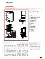
Layout of boiler
The boiler consists of the
following
PDLQFRPSRQHQWV
1
2
3
4
5
6
7
9
10
11
12
13
14
15
16
17
19
20
21
22
Casing
Access door for Control panel
Flue gas connection (+ test point)
Air intake connection (+ test point)
Flow water connection
Return water connection
Gas connection
Condensate syphon
,QSXWIRUZLULQJ
Connection for safety valve
&RQQHFWLRQIRU¿OOGUDLQYDOYH
Manometer
Fan
Gas valve
,JQLWLRQDQGLRQLVDWLRQHOHFWURGHV
Heat exchanger
,QVSHFWLRQZLQGRZ
,JQLWLRQWUDQVIRUPHU
Electrical input connections
Controller
Condens tray
Control Panel
Construction
Layout of boiler
Operating principle
1
2
4
3
12
10
5
8
7 9
6
11
16
22
20
19
21
13
14
18
15
17
R40


