background image


ECONOFLAME R6000 LMS 

GAS FIRED  

CONDENSING BOILERS 


INSTALLATION,OPERATION & MAINTENANCE  

DOCUMENTATION 


STOKVIS ENERGY SYSTEMS


96R WALTON ROAD 

EAST MOLESEY 

SURREY 

KT8 0DL 

TEL: 020 87833050 / 08707 707 747 

FAX: 020 87833051 / 08707 707 767 

E-MAIL:


info@stokvisboilers.com


WEBSITE:


www.stok

v

isboilers.com


DOC3070 R6000 BA 


Summary of Contents for ECONOFLAME R6000 LMS

Page 1: ...TALLATION OPERATION MAINTENANCE DOCUMENTATION STOKVIS ENERGY SYSTEMS 96R WALTON ROAD EAST MOLESEY SURREY KT8 0DL TEL 020 87833050 08707 707 747 FAX 020 87833051 08707 707 767 E MAIL info stokvisboiler...

Page 2: ...iler for first startup 15 Combustion analysis 16 Check water flow 17 Check functionality of safety devices 18 Gas tightness check 18 Boiler shut down 18 Commissioning protocol 19 Operating instruction...

Page 3: ...he R6000 boiler is CE approved and applies to the following European standards 92 42 EEC Boiler efficiency directive 2009 142 EEC Gas appliance directive 73 23 EEC Low voltage directive 2004 108 EEC E...

Page 4: ...sted by the system This is done by controlling the speed of the fan As a result the Whirlwind mix ing system will adapt the gas ratio to the chosen fan speed in order to main tain the best possible co...

Page 5: ...min C 56 30 Flue gas quantity max min m3 h 238 40 318 69 397 69 477 69 636 134 795 134 901 134 CO2 level natural gas H E L LL max min 10 2 9 4 CO2 level liguid gas P max min 11 9 10 0 NOx level max m...

Page 6: ...5 215 215 215 B3 mm 260 260 260 310 310 310 310 B4 mm 260 260 260 490 490 490 490 B5 mm 130 130 130 245 245 245 245 D1 mm Diam 130 150 150 150 200 200 200 D2 mm Diam 150 150 200 200 250 250 250 W1 R D...

Page 7: ...the boiler Syphon for condensate connection 1 Cardboard box on top of heatexchanger under casing Conversion kit for natural gas L and propane incl instruction 1 Cardboard box on top of heatexchanger...

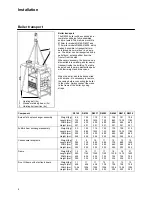
Page 8: ...R6142 R6190 R6237 R6285 R6380 R6475 R6539 Burner 1st heat exchanger assembly Weight kg Length mm Width mm Height mm 86 735 400 321 100 885 400 321 112 1035 400 321 135 735 680 321 158 885 680 321 181...

Page 9: ...on Removing the casing 9 Boiler transport Remove the casing before transporting the boiler in order to avoid damage to the casing parts during transportation Removing the casing is done as fol lows 1...

Page 10: ...e the recommended minimum clea rance in the picture When the boiler is positioned with less free space mainte nance activities will be more difficult Once the boiler is in the correct positi on the wo...

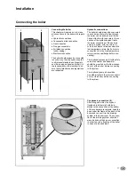
Page 11: ...ler connections If the boiler is used in a system with two return cir cuits the common return becomes the low temperature return the 2nd return connection 6 is the high temperature return remove cap f...

Page 12: ...onal regulations Construct the flue gas system as short as possible for maximum length see planner documentation Construct horizonal ways with a mini mum angle of 3 Air intake connection 3 The air int...

Page 13: ...ydraulic system Check if the boiler is hydraulically con nected to the system in such way that water flow can be secured at all times during burner operation The water flow is supervised by the water...

Page 14: ...ned Consult the conversion kit instruction if the boiler is to be installed with natural gas L or LPG Condensate connection Remove the syphon 2 from the con densate connection Fill it with water and p...

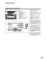
Page 15: ...n make sure the pump runs in the right direction Release all air from the pump motor It s recommended to put the boiler on 50 load after the first startup as this is the best starting point to do a pr...

Page 16: ...settings with the flat adjustment screw on the outlet of the gas valve 2 Combustion settings for natural gas G20 G25 R6142 R6539 CO2 min 9 4 0 2 COmin ppm 30 Combustion settings for LPG G31 Convert b...

Page 17: ...when the boiler is running on 100 load The nominal T is 20K and must be at least between 15K and 25K for secure boiler operation An indication of the actual flow rate can be found with the follo wing...

Page 18: ...fety devices have to be checked on good functioning Safety devices on a standard boiler are a water flow tem perature sensor fluegas temperature sensor water flow switch minumum gas pressure switch an...

Page 19: ...Plated heat exchanger Water flow m3 h Bypass boiler Pump setting Other Safety devices High limit setting C Water flow sensor checked Temp limiter setting C Fluegas sensor checked Min gas pressure swit...

Page 20: ...mfort sun 24 7 heating in comfort mode Reduction moon 24 7 heating in reduced mode Standby heating off frost protection activated Display L Info mode G Display possibility of following info without in...

Page 21: ...enu with ESC button Commissioning Expert choose user level confirm with OK button choose menu confirm with OK button choose parameter confirm with OK button change value with wheel confirm with OK but...

Page 22: ...Winter automatic switching activated ECO functions activated Safety mode on with Heating off Temperature by frost protection Safety functions activated Controller Stop mode Press button 3 sec Press b...

Page 23: ...desired values External temperature setpoint via 0 10Vdc analogue signal H1 terminals 109 and 110 Function not active when setpoint 5 C Function active when setpoint 5 C 1 Ensure that the analogue 0 1...

Page 24: ...ctrodes Clean the condensate receptacle Clean and refill the syphon Inspect the combustion chamber clean if necessary Check the water pressure of the sys tem Check the water quality of the system wate...

Page 25: ...on when the cleaning is finished Connect the plug of the fluegas temperature sensor Inspection of combustion chamber The inspection opening is positioned on the left hand side of the boiler Remove the...

Page 26: ...0 load is recommended Consult the chapter commissioning combustion analysis for more detailed information Gas pressure Check the dynamic pressure of the gas supply to the boiler when the boiler is run...

Page 27: ...ety devices High limit setting C Water flow sensor checked Temp limiter setting C Fluegas sensor checked Min gas pressure switch setting mbar Water flow switch checked Ignition time burner sec Combust...

Page 28: ...1 sensor error 65 Room temperature 2 sensor error 70 Buffer storage tank temperature 1 sensor error 71 Buffer storage tank temperature 2 sensor error 72 Buffer storage tank temperature 3 sensor error...

Page 29: ...ging temperature sensor error 324 BX same sensors 325 BX extension module same sensors 326 BX mixing group same sensors 327 Extension module same function 328 Mixing group same finction 329 Extension...

Page 30: ...r 349 Buffer return valve Y15 not available 350 Puffer address sensor 351 Primary controller system pump address error 352 Pressureless header address error 353 Common flow sensor B10 not available 37...

Page 31: ...be switched off Measure close to the sensor in order to avoid value deviations 30 0 5000 10000 15000 20000 25000 30000 35000 40000 45000 50000 55000 60000 10 0 10 20 30 40 50 60 70 80 90 100 110 Temp...

Page 32: ...andards EN 298 EN 656 EN 15420 EN 55014 1 2 EN 61000 3 2 3 EN 60 335 1 2 And in accordance with the guidelines of directives 92 42 EEC boiler efficiency directive 2009 142 EEC gas appliance directive...

Page 33: ......

Reviews: