14
Installation
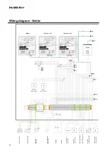
Wiring diagram - Boiler
Ma
in
ga
s v
a
lv
e
Pressure sw
itch
R
oom fan
(2
A
ma
x
.)
M
od. feed
back
0-
10V D
C
LPB Bus
Enabl
e
Ex
t. Setp
oint
0-
10V D
C
Outside
tem
p
. s
ensor
D
H
W
Ther
mosta
t
or
D
H
W
te
mp.
sens
or
Min
. ga
s
pressure sw
itch
C
om
m
on
f
low
tem
p
. s
ensor
Return
temp. sensor
Flow
temp. sensor
Heating circuit 2
Heating circuit 1


