background image

Commissioning 


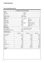
Commissioning protocol  

24 


Commissioning Protocol R600


Project


Boiler type 


Project 


Serial number 


Address 


Year 


City 


Nominal load (Hi) 

[kW] 

Date 


Nominal output (Hi) 

[kW] 

Engineer 


System  


Water pressure 

[bar] Installati-

on:       

Roof top 


Water pH 

[-] 

Ground floor 


Water hardness 

[dºH] 

Basement 


Water chloride 

[mg/l] 

Other:   ......................... 


Water 

T full load 

[ºC] 

Hydrau-
lics:       

Low velocity header 


Water 

p

boiler


[kPa] 

Plated heat exchanger 


Water flow 

[m

3

/h] Bypass 

boiler 


Pump setting 

[-] 

Other:   ......................... 


Safety devices


High limit setting 

[ºC] 

Water flow sensor checked 


Temp. limiter setting 

[ºC] 

Fluegas sensor checked 


Min. gas pressure switch setting 

[mbar] 


Ignition time burner 

[sec] 


Combustion analysis


100% load


50% load


Min. load


Gas consumption 

[m

3

/h] [m

3

/h] [m

3

/h] 

Gas pressure 

[mbar] 

[mbar] 

[mbar] 

CO

2

 [%] 

[%] 

[%] 

O

2

 [%] 

[%] 

[%] 

CO [ppm] 

[ppm] 

[ppm] 

NOx [ppm] 

[ppm] 

[ppm] 

T

atmospheric

 [ºC] 

[ºC] 

[ºC] 

T

fluegas

 [ºC] 

[ºC] 

[ºC] 

T

water, flow

 [ºC] 

[ºC] 

[ºC] 

T

water, return

 [ºC] 

[ºC] 

[ºC] 

Ionisation current 

[µA] 

[µA] 

[µA] 

p

fan

 [mbar] 

[mbar] 

[mbar] 

p

top panel

 [mbar] 

[mbar] 

[mbar] 

p

combustion chamber

 [mbar] 

[mbar] 

[mbar] 

Remarks


Summary of Contents for R601

Page 1: ...ing Installation Operation Maintenance Manual STOKVIS ENERGY SYSTEMS 96R Walton Road East Molesey Surrey KT8 0DL Tel 020 8783 3050 0870 7707747 Fax 020 8783 3051 0870 7707767 E Mail info stokvisboilers com Website www stokvisboilers com 420010567300 12 2013 ...

Page 2: ...2 ...

Page 3: ...ake connections 19 Prepare boiler for first startup 20 Combustion analysis 20 Check water flow 22 Check functionality of safety devices 23 Gas tightness check 23 Boiler shut down 23 Commissioning protocol 24 Operating instructions Controls 25 Display Programming 26 Overview of main functions 27 Maintenance Checklist 28 Replacing the electrodes 28 Cleaning the condensate receptacle 29 Cleaning and ...

Page 4: ... Gas appliance directive 2006 95 EEC Low voltage directive 2004 108 EEC EMC directive EN 656 Gas fired central heating boilers Type B boilers of nominal heat input exceeding 70 kW but not exceeding 300 kW EN 15420 Gas fired central heating boilers Type C boilers of nominal heat input exceeding 70 kW but not exceeding 1000 kW EN 15417 Gas fired central heating boilers Specific requirements for cond...

Page 5: ...ested by the system This is done by controlling the speed of the fan As a result the Whirlwind mix ing system will adapt the gas ratio to the chosen fan speed in order to main tain the best possible combustion fig ures and therewith the best efficiency The flue gases created by the combus tion are transported downwards through the boiler and leave at the back side into the chimney connection The L...

Page 6: ...max min ºC 56 30 Flue gas quantity max min m3 h 238 40 318 69 397 69 477 69 636 134 795 134 901 134 CO2 level natural gas G20 G25 max min 10 2 9 4 CO2 level G31 max min 11 9 10 0 NOx level max min mg kWh 35 15 CO level max min mg kWh 14 8 Max permissible flue resistance max min Pa 160 10 160 10 200 10 200 10 200 10 250 10 250 10 Water volume l 27 31 35 61 68 75 82 Water pressure max min bar 8 1 Ma...

Page 7: ... 215 215 B3 mm 260 260 260 310 310 310 310 B4 mm 260 260 260 490 490 490 490 B5 mm 130 130 130 245 245 245 245 D1 mm Diam 130 150 150 150 200 200 200 D2 mm Diam 150 150 200 200 250 250 250 W1 R DN R2 R2 R2 DN65 PN16 W2 R DN R2 R2 R2 DN65 PN16 G R R 3 4 R 1 R 1 R 1 R 1 1 2 1 Electrical connections 2 Gas supply 3 Water supply 4 Water return Cold 5 Air Intake under casing 6 Water 2nd return optional ...

Page 8: ...r condensate connection 1 Cardboard box on top of heatexchanger under casing Conversion kit for natural gas L and propane incl instruction 1 Cardboard box on top of heatexchanger under casing Operation and Installation manual 1 Map attached to back panel of the boiler Spare parts list 1 Map attached to back panel of the boiler Wiring diagram 1 Map attached to back panel of the boiler Accessories A...

Page 9: ...t R601 R602 R603 R604 R605 R606 R607 Burner 1st heat exchanger assembly Weight kg Length mm Width mm Height mm 86 735 400 321 100 885 400 321 112 1035 400 321 135 735 680 321 158 885 680 321 181 1035 680 321 198 1185 680 321 2nd 3rd heat exchanger assembly Weight kg Length mm Width mm Height mm 90 735 400 244 103 885 400 244 116 1035 400 244 150 735 680 244 170 885 680 244 198 1035 680 244 219 118...

Page 10: ...ion Removing the casing 10 Boiler transport Remove the casing before transporting the boiler in order to avoid damage to the casing parts during transportation Removing the casing is done as fol lows 1 4 5 6 2 3 ...

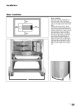
Page 11: ...te the recommended minimum clea rance in the picture When the boiler is positioned with less free space mainte nance activities will be more difficult Once the boiler is in the correct posi tion the wooden blocks 1 should be removed and the adjustable feet 2 with vibration absorption dampers should be adjusted to the right height Water and gas connections should be done after mounting the feet as ...

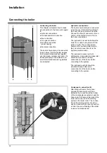
Page 12: ... boiler connections The optional 2nd return kit allows the boiler to be used in a system with two return circuits The common return becomes the low temperature return the 2nd return connection 6 is the high temperature return The optional accessory kit with safety valve manometer and deaerator should be mounted on the flow connection 4 of the boiler before connecting to the system The optional pum...

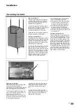
Page 13: ...nal regulations Construct the flue gas system as short as possible for maximum length see planner documentation Construct horizonal ways with a mini mum angle of 3º Air intake connection 3 The air intake can be connected in ca se of room sealed installation The co ver 3 must be disassembled in order to connect the air intake piping to the connector inside the boiler The diame ter should be calcula...

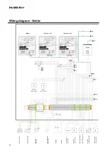
Page 14: ...ure switch Room fan 2A max Mod feedback 0 10V DC LPB Bus Enable Ext Setpoint 0 10V DC Outside temp sensor DHW Thermostat or DHW temp sensor Min gas pressure switch Common flow temp sensor Return temp sensor Flow temp sensor Heating circuit 2 Heating circuit 1 ...

Page 15: ...Installation Wiring diagram Boiler 15 Flue gas temp sensor DHW Pump 230V 1A max Boiler pump Bypass pump Lockout input ...

Page 16: ...ing diagram Accessories 16 Flow temp sensor Mixing valve control 0 5A max Heating circuit pump 2A max Flow temp sensor Mixing valve control 0 5A max Heating circuit pump 2A max Alarm Heating circuit 2 Heating circuit 1 ...

Page 17: ...Installation Wiring diagram Accessories 17 Gas valve Leakage test STL Boiler temp Max water pressure switch Max gas pressure switch Remove jumper when connecting device Max water pressure switch ...

Page 18: ...sonnel only Failure to respect this condition makes the guarantee void A protocol of the commissioning should be filled out see end of this chapter for example of commissioning protocol This chapter explains the commissio ning of the boiler with the standard boi ler controller When an additional sys tem controller is installed please refer to its manual for commissioning the controller In installa...

Page 19: ...ned Consult the conversion kit instruction if the boiler is to be installed with natural gas L or LPG Condensate connection Remove the syphon 2 from the con densate connection Fill it with water and place it back in the original posi tion Make sure the syphon is filled before starting the boiler in order to prevent flue gases dischar ging through the condensate connec tion Flue and air intake conn...

Page 20: ...n make sure the pump runs in the right direction Release all air from the pump motor It s recommended to put the boiler on 50 load after the first startup as this is the best starting point to do a proper combustion analysis This can be done with the following procedure Push button I 3 Sek the boiler goes into controller Stopp mode Push the Info button G the actual boiler load appears in the displ...

Page 21: ...he settings with the flat adjustment screw on the outlet of the gas valve 2 Combustion settings for natural gas G20 G25 R601 R607 CO2 min 9 4 0 2 Combustion settings for LPG G31 Convert boiler before operation see coversion kit instruction R601 R607 CO2 min 10 0 0 2 Combustion check at minimum load Switch the boiler to minimum load 0 Check the combustion settings the same way as described for full...

Page 22: ...en the boiler is running on 100 load The nominal T is 20K and must be at least between 15K and 25K for secure boiler operation An indication of the actual flow rate can be found with the follo wing calculation see table below for nominal data qactual pmeasured pnominal qnominal m3 h p measurement Check the pressure difference over the boiler p flow return when the boiler pump is running burner on ...

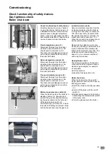
Page 23: ...s All safety devices have to be checked on good functioning Safety devices on a standard boiler are a water flow tem perature sensor fluegas temperature sensor minumum gas pressure switch and ionisation electrode These devices can be checked as described below Ionisation electrode 6 Remove electrical connection from the ionisation electrode while the boiler is running the boiler will go in lockout...

Page 24: ...ted heat exchanger Water flow m3 h Bypass boiler Pump setting Other Safety devices High limit setting ºC Water flow sensor checked Temp limiter setting ºC Fluegas sensor checked Min gas pressure switch setting mbar Ignition time burner sec Combustion analysis 100 load 50 load Min load Gas consumption m3 h m3 h m3 h Gas pressure mbar mbar mbar CO2 O2 CO ppm ppm ppm NOx ppm ppm ppm Tatmospheric ºC º...

Page 25: ...mfort sun 24 7 heating in comfort mode Reduction moon 24 7 heating in reduced mode Standby heating off frost protection activated Display L Info mode G Display possibility of following info without influence on boiler control temperatures operation mode Heating DHW error code Room temperature control C for changing room comfort tempe rature for changing settings when pro gramming Deaeration mode E...

Page 26: ...nu with ESC button Commissioning Expert choose user level confirm with OK button choose menu confirm with OK button choose parameter confirm with OK button change value with wheel confirm with OK button return to main menu with ESC button Programming Select turn left right Quit menu Reset Press OK 1x Press OK 1x Press INFO 4 sec Default mode buttons Heating to comfort setpoint Info level activated...

Page 27: ... Winter automatic switching activated ECO functions activated Safety mode on with Heating off Temperature by frost protection Safety functions activated Controller Stop mode Press button 3 sec Press button 3 sec again 304 Controller Stopp mode insert setpoint after 3 sec Main menu appears Info display Press button 1x Press button 1x again Press button 1x again Press button 1x INFO Segment displaye...

Page 28: ...sate receptacle Clean and refill the syphon Inspect the combustion chamber clean if necessary only with compressed air and or vacuum cleaner Check the water pressure of the sys tem Check the water quality of the system water as well as supply water Check the water flow rate through the boiler Check correct the combustion values at full and mimimum load with a com bustion analyzer Check the gas pre...

Page 29: ...onnect the plug of the fluegas tem perature sensor Inspection of combustion chamber The sight glass 5 is positioned on the left hand side of the boiler Inspect the combustion chamber by viewing through the sight glass Cleaning can be done with water Remove the viewing mirror and glass from the sight glass holder Stick a garden hose through the sight glass holder and rinse the heat exchanger with w...

Page 30: ...50 load is recommended Consult the chapter commissioning combustion analysis for more detailed information Gas pressure Check the dynamic pressure of the gas supply to the boiler when the boiler is running at full load In case of a boiler cascade all boilers should be running at full load See technical data for re quired values Gas tightness check Check the tightness of all sealed con nections wit...

Page 31: ...afety devices High limit setting ºC Water flow sensor checked Temp limiter setting ºC Fluegas sensor checked Min gas pressure switch setting mbar Ignition time burner sec Combustion analysis 100 load 50 load Min load Gas consumption m3 h m3 h m3 h Gas pressure mbar mbar mbar CO2 O2 CO ppm ppm ppm NOx ppm ppm ppm Tatmospheric ºC ºC ºC Tfluegas ºC ºC ºC Twater flow ºC ºC ºC Twater return ºC ºC ºC Io...

Page 32: ...e 1 sensor error 65 Room temperature 2 sensor error 70 Buffer storage tank temperature 1 sensor error 71 Buffer storage tank temperature 2 sensor error 72 Buffer storage tank temperature 3 sensor error 73 Collector temperature 1 sensor error 74 Collector temperature 2 sensor error 82 LPB address collision 83 BSB wire short circuit 84 BSB address collision 85 BSB RF communication error 91 EEPROM er...

Page 33: ...ng temperature sensor error 324 BX same sensors 325 BX extension module same sensors 326 BX mixing group same sensors 327 Extension module same function 328 Mixing group same finction 329 Extension module mixing group same function 330 Sensor BX1 no function 331 Sensor BX2 no function 332 Sensor BX3 no function 333 Sensor BX4 no function 334 Sensor BX5 no function 335 Sensor BX21 no function EM1 E...

Page 34: ...349 Buffer return valve Y15 not available 350 Puffer address sensor 351 Primary controller system pump address error 352 Pressureless header address error 353 Common flow sensor B10 not available 371 Flow temperature 3 heating circuit 3 supervision 372 Limit thermostat heating circuit 3 373 Extension module 3 error collective error 386 Fan speed has lost valid range 388 DHW error no function 426 F...

Page 35: ... be switched off Measure close to the sensor in order to avoid value deviations 0 5000 10000 15000 20000 25000 30000 35000 40000 45000 50000 55000 60000 10 0 10 20 30 40 50 60 70 80 90 100 110 Temperature ºC Resistance Ohm 500 1000 1500 2000 2500 3000 3500 4000 4500 5000 5500 6000 6500 7000 7500 20 10 0 10 20 30 40 Temperature ºC Resistance Ohm NTC 1kΩ temperature sensor outdoor sensor NTC 10kΩ te...

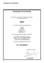
Page 36: ...standards EN 298 EN 656 EN 15420 EN 55014 1 2 EN 61000 3 2 3 EN 60 335 1 2 And in accordance with the guidelines of directives 92 42 EEC boiler efficiency directive 2009 142 EEC gas appliance directive 2006 95 EEC low voltage directive 2004 108 EEC EMC directive This product is designated with CE number CE 0063BS3840 Kerkrade 17 04 2013 A J G Schuiling Plant Manager ...

Page 37: ......

Page 38: ...IS ENERGY SYSTEMS 96R Walton Road East Molesey Surrey KT8 0DL Tel 020 8783 3050 0870 7707747 Fax 020 8783 3051 0870 7707767 E Mail info stokvisboilers com Website www stokvisboilers com 420010567300 12 2013 ...

Reviews: