16
3.3 ELECTRICAL CONNECTION
Electrical systems of thermal pl ants designed only for heating purposes
must comply with numerous le-
gal regulations which apply to in general as well as specifically to each application or fuel type.
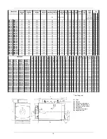
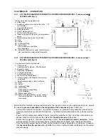
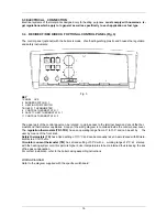
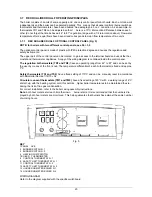
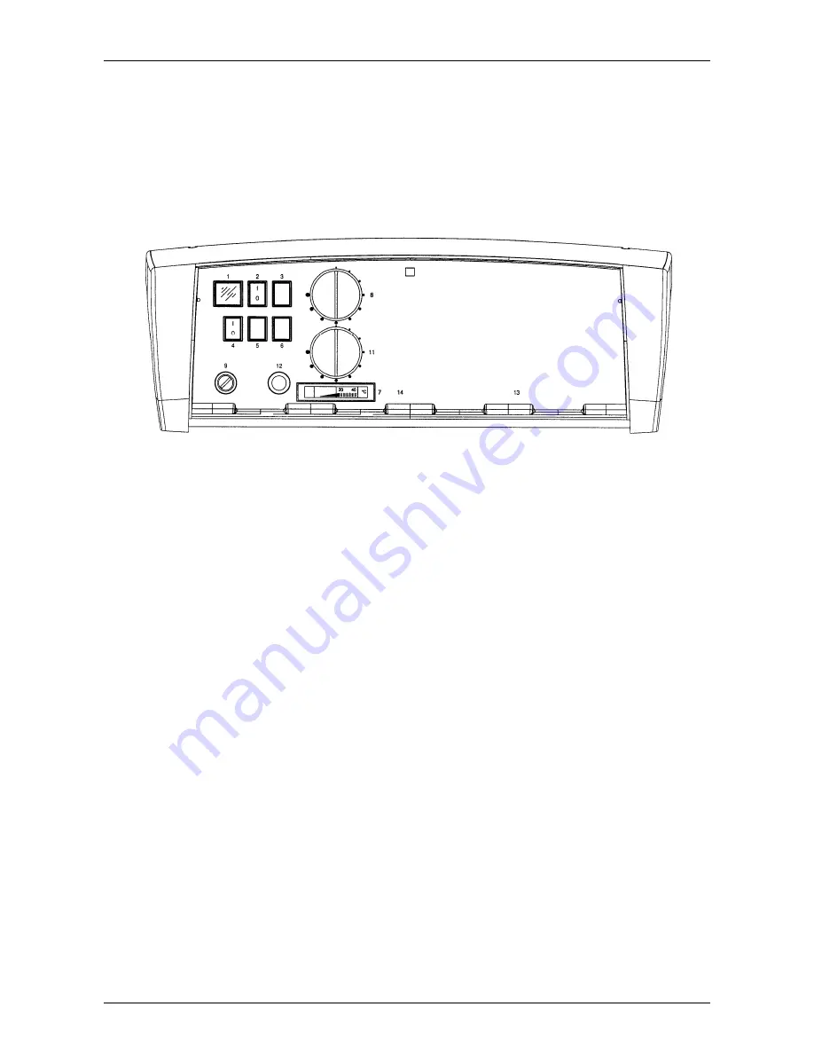
3.4 REX/REX F/REX K/REX K F OPTIONAL CONTROL PANEL (Fig. 3)
The control panel (optional) with the boilers is made of self-extinguishing plas tic and houses the regulation
and safety instruments:
Fig. 3
KEY
1 PANEL LIVE
2 BURNER SWITCH N. 1
4 HEATING PUMP SWITCH
7 BOILER THERMOMETER
8 CONTROL THERMOSTAT N. 1
9 SAFETY LIMIT THERMOSTAT N. 1
11 CONTROL THERMOSTAT N. 2
The upper part of the control panel can be rotated to gain access to the terminal board and uncoil the ther-
mostat and thermometer capillaries. A copy of the wiring diagram is contained inside the control panel cover.
The
regulation thermostats (TR1-TR2)
have an operating range from 60° to 100° and can be set by
the
user by means of the front knob.
Safety thermostats (TS)
has a fixed setting of 110°C and can be manually reset in accordance with Ministe-
rial Decree 1/12/75 «R».
Circulator consent thermostat (TM)
has a fixed setting of 50°C with a working range of 6°C: at start-up,
with the heating system cold, this permits higher boile r temperatures to be maintained thus reducing the risk
of flue gas condensation.
For correct installation, refer to the boiler casing assembly instructions.
WIRING DIAGRAM
Refer to the diagram supplied with the specific switchboard.
Summary of Contents for REX F
Page 1: ...TECHNICAL MANUAL REX REX F REX K REX K F REX DUAL REX DUAL F PRESSURISED STEEL BOILERS...
Page 2: ......
Page 18: ...18 1 2 6 3 4 5 9...
Page 30: ......
Page 32: ...ASSEMBLY INSTRUCTIONS STAVES LINING...
Page 33: ......


