Stollmann
E + V GmbH
C11/G2
User Guide
Author: ta
Date saved: 06.04.09
Ref: C11G2_User_Guide_r02.doc
Revision: r02
Page 18 of 22
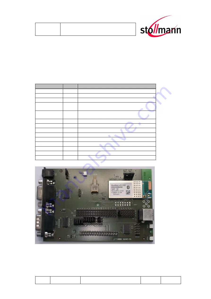
4.7 Default Factory Configuration
The C11/G2 supports SPP. It is preconfigured to DCE mode, using serial
control lines and external power supply. The jumpers are configured as described
below:
Jumper Number Position Description
J1.2
2-3
PIO9 connected to LED2
J1.4
2-3
PIO7 connected to LED1
J1.5
2-3
PIO 6 connected to RI on DTE/DCE socket
J1.6
2-3
PIO 14 connected to DTR (DTE) and DSR (DCE)
output on DTE/DCE socket
J1.7
2-3
PIO 13 connected to DSR (DTE) and DTR (DCE)
input
J1.8
2-3
PIO 15 connected to DCD for DTE and DCE
J1.9
1-2
RTS connected to DTE/DCE socket
J1.10
1-2
TXD connected to DTE/DCE socket
J1.11
1-2
RXD connected to DTE/DCE socket
J1.12
1-2
CTS connected to DTE/DCE socket
J3.7
1-2
DCE Socket selected
J4
2-3
Power socket as power input
J5
1-2
Power supplied to C11/G2 VDD
J5
3-4
Power supplied to C11/G2 VDD RF
Figure: C11/G2 default configuration


