S/AI
Hardware Reference
Page 20 of 52
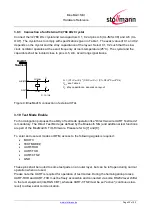
3.9.3 Connection of an External 32,768 kHz Crystal
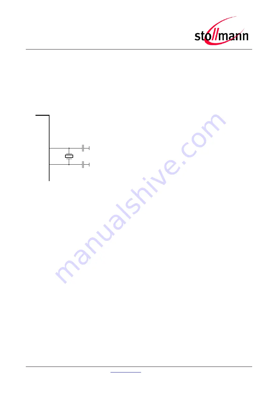
Connect the 32,768 kHz crystal and two capacitors C1, C2 at pins A-6 (XL-IN/SLCK) and A-5 (XL-
OUT). The crystal has to comply with specifications given in Table 1. The exact value of C1 and C2
depends on the crystal and the stray capacitance of the layout. Select C1, C2 such that the slow
clock oscillator operates at the exact frequency at room temperature (25°C). The crystal and the
capacitors shall be located close to pins A-5, A-6. Avoid long signal traces.
C
L
= (C1+C
pin
+C
s
) * (C2+C
pin
+C
s
) / (C1+C2+2*C
pin
+2*Cs)
C
pin
: see Table 4
C
s
: stray capacitance, depends on layout
Figure 9: S connection of external XTAL
3.10 Test Mode Enable
For homologation purposes the ability of testmode operation like "Direct two wire UART Testmode"
is mandatory. The Direct Test Mode (as defined by the Bluetooth SIG) and additional test functions
are part of the S TIO-Firmware. Please refer to [7] and [8].
To enter and use test modes or DTM, access to the following signals is required:
•
BOOT0
•
TESTMODE#
•
UART-RXD
•
UART-TXD
•
UART-CTS#
•
GND
These pins shall be routed to some test pads on an outer layer, but can be left open during normal
operation when not used.
Please note the UART is required for operation of test modes. During the homologation process,
UART-RXD and UART-TXD must be freely accessible and connected via some RS232 level shifter
to the test equipment (like R&S CBT), whereas UART-CTS# must be set "active" (continuous low-
level) to allow serial communication.
XL-IN/SLCK
S
A-6
Slow Clock
XL-OUT
A-5
32,768kHz
CL: 9pF
C1
C2
C1, C2 ~ 12pF


