background image


TA+P2I 

User Manual 


Release r06 

www.stollmann.de 

Page 2 of 18 


Note 

This device was developed for the purpose of communication in an office 
environment. It is intended solely for our industrial clients for physical integration into 
their own technical products after careful examination by experienced technical 
personnel for its suitability for the intended purpose. The device was not developed 
for or intended for use in any specific customer application. The firmware of the 
device may have to be adapted to the specific intended modalities of use or even 
replaced by other firmware in order to ensure flawless function in the respective 
areas of application. Performance data (range, power requirements, etc.) may 
depend on the operating environment, the area of application, the configuration, and 
method of control, as well as on other conditions of use; these may deviate from the 
technical specifications, the Design Guide specifications, or other product 
documentation. The actual performance characteristics can be determined only by 
measurements subsequent to integration. Variations in the performance data of 
mass-produced devices may occur due to individual differences between such 
devices. Device samples were tested in a reference environment for compliance 
with the legal requirements applicable to the reference environment. No 
representation is made regarding the compliance with legal, regulatory, or other 
requirements in other environments. No representation can be made and no 
warranty can be assumed regarding the suitability of the device for a specific 
purpose as defined by our customers. Stollmann reserves the right to make changes 
to the hardware or firmware or to the specifications without prior notice or to replace 
the device with a successor model. Of course, any changes to the hardware or 
firmware of any devices for which we have entered into a supply agreement with our 
customers will be made only if, and only to the extent that, such changes can 
reasonably be expected to be acceptable to our customers. No general commitment 
will be made regarding periods of availability; these must be subject to individual 
agreement. All agreements are subject to our Terms and Conditions for Deliveries 
and Payments, a copy of which is available from Stollmann. 

Copyright © 2005-2008 Stollmann E+V GmbH 


Trademarks 

The Bluetooth

®


word mark and logos are owned by the Bluetooth SIG, Inc. and any 

use of such marks by Stollmann E+V GmbH is under license. Other trademarks and 
trade names are those of their respective owners.


Summary of Contents for TA+P2I

Page 1: ...TA P2I Adapting ISDN Phones to POTS FXS User Manual Release r06...

Page 2: ...ferences between such devices Device samples were tested in a reference environment for compliance with the legal requirements applicable to the reference environment No representation is made regardi...

Page 3: ...age of the TA P2I 9 3 1 Incoming call 10 3 2 Outgoing call 11 3 3 Call waiting 11 3 4 Call Hold Enquiry 11 3 5 Three party conference 12 3 6 Call forwarding 12 3 7 Additional supplementary services 12...

Page 4: ...ogue interfaces POTS FXS The analogue lines of the TA P2I react like standard analogue phones und have to be connected with the FXO ports of the switching system or adapter The ISDN interface has iden...

Page 5: ...ins the following parts TA P2I adapter External power supply cable length approx 1 85m Two cable for the analogue interfaces cable length approx 1 00m This user manual Quick installation guide 2 2 Pro...

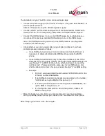
Page 6: ...rom both lines it is necessary to delete all still activated MSN settings inside the ISDN phone o If one ISDN phone shall react only to the phone numbers of one of the analogue lines of the cable mode...

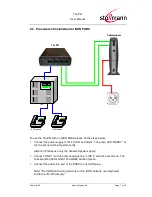
Page 7: ...supply to the TA P2I and mains The green LED READY at the front panel will be lit permanently Attention Please use only the delivered power supply Connect LINE 1 with the first analogue line LINE 2 wi...

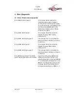
Page 8: ...e ERROR Hardware error the TA P2I cannot be used LINE1 Lit The analogue line 1 is connected to a working analogue interface Blinking The analogue line 1 is connected to a working analogue interface bu...

Page 9: ...se many supplementary services known from the ISDN also via the analogue lines the services have to be activated on the analogue lines The TA P2I supports the following supplementary services Outgoing...

Page 10: ...g calls on analogue line 1 Phone with MSN 2 is ringing on incoming calls on analogue line 2 For experts only If a phone number according to the call number of the analogue lines shall be used you have...

Page 11: ...ia ISDN and the cable modem The cable modem establishes the voice connection via VoIP An example of an outgoing call attempt using the key looks like follows phone number i e 123456789 Important Some...

Page 12: ...ly possible by using the appropriate keys of the ISDN phone i e 21 phone number Activation and deactivation by using the menu keys of an ISDN phone or an ISDN PABX is not possible 3 7 Additional suppl...

Page 13: ...t Is the LINE1 LED blinking green The analogue line 1 is connected to a working analogue interface but there is no dial tone Is the LINE2 LED lit green If not please check the connection between the p...

Page 14: ...he setting of the MSN correct Check the setting of the MSN in the ISDN phone and the TA P2I Please refer additionally to chapter incoming call 4 4 FAQ The TA P2I supports all ISDN phones and ISDN PABX...

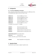
Page 15: ...x Set up first MSN xxx for line 2 00000112xxx Set up second MSN xxx for line 2 00000122xxx Set up third MSN xxx for line 2 The MSN xxx may consist of 1 20 digits 000002011 Barring incoming calls for l...

Page 16: ...ignment analogue plug 6 pin RJ11 Pin Signal a b 1 Not connected 2 Not connected 3 a TIP 4 b RING 5 Not connected 6 Not connected 7 2 ISDN ports Function TA P2I ISDN interface 1 x I 430 LT S mode S Bus...

Page 17: ...www stollmann de Page 17 of 18 Pin assignment ISDN plug 8 pin RJ45 ITU I 430 ISO 8877 Pin Signal S0 1 Not connected 2 Not connected 3 2a Rx Receive 4 1a Tx Transmit 5 1b Tx Transmit 6 2b Rx Receive 7...

Page 18: ...ified behavior depending on the MSN settings during outgoing call New parameter for setting the year Modified LED behavior for LINE1 LINE2 ISDN1 ISDN2 r06 Jun 2008 ta Revised chapter Call Forwarding I...

Reviews: