- 20 -
MAINTENANCE
INTRODUCTION
Congratulations on your purchase of the LJS2000
Lift Jockey! Youve made an excellent choice. The
Lift Jockey is specifically designed for lifting and
transporting a wide variety of materials on your job
site. Your new Lift Jockey comes standard with the
following features:
Mast Height -
Choice of three (3) interchangeable,
rugged, high lift masts. Lift from heights of 76 to
96. Masts tilt forward and reverse for easy han-
dling and discharging of loads.
Load/Speed Capacity
- Lifts and moves up to 1,000
lbs. at speeds up to 3 mph for getting around any site
faster.
Controls
- Forward and reverse travel controlled by
handle grips on steering handle. All controls--horn,
throttle, tilt control and lift/lower are within opera-
tors reach. Power controls automatically return to
neutral position when released.
Hydrostatic Drive
- Clean, quiet with totally
enclosed hydraulic drive circuit. Provides reliability,
lower maintenance and longer life.
Engine Cowl
- Allows easy access to all mainte-
nance points for quick service. Provides optimum
airflow for cooler running and longer life on compo-
nents.
Lift Points
Provide two means to lift with forks or
a hoist. Two sets of fork loops are located width-
wise under the frame and a lift eye under the front
hood. Allows easy transport for unit and placing on
elevated platforms.
Tires
- Foam-filled drive and load tires provide the
added toughness and reliability on a job site.
Forks
- Four interchangeable, adjustable fork options
provide efficient handling of all types of loads.
Choose from round block forks or box forks for
several different pallet sizes. The 22 inch invertable
box forks can be used to increase effective lifting
height for applications such as setting lintels.
KNOW YOUR LIFT
Read and understand the owners manual before
starting the unit. Make sure you understand the
purpose of every control. Refer to ASME Standard
B56.1-2000 amended with B56.19-2001 Standard
for forklift safety training. When operating the unit,
remember the capacity it can carry and adjust speed
and load for changing conditions.
Pre-Operation Checklist
Upon receipt of your
Lift Jockey,
CAREFULLY CHECK FOR ANY
FREIGHT DAMAGE.
Any damage should be
immediately reported to the carrier and a claim
registered.
The Lift Jockey is manufactured to the strictest
specifications and inspection procedures. After
inspecting the quality of the workmanship of your
machine, please complete and return the tag on the
machine with the assemblers signature with your
findings to Stone. We value our customers input
and welcome any and all comments on how the
product may serve you better.
The following instructions were compiled to provide
you information on how to obtain long and trouble-
free use of the unit. Read and understand the
owners manual before starting the unit. Make sure
you understand the purpose of every control. When
operating the unit, know the capacity it can carry
and adjust the speed and load for changing condi-
tions.
Intro/Know Your Lift
Summary of Contents for Lift Jockey LJS2000
Page 2: ......
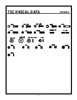
Page 13: ...13 TECHNICAL DATA Hardware...
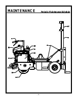
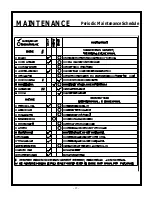
Page 34: ...34 MAINTENANCE Periodic Maintenance Schedule...
Page 35: ...35 MAINTENANCE Periodic Maintenance Schedule...
Page 38: ......
Page 40: ...40 PARTS LIST Tilt Cylinder Front Cowl Assembly...
Page 41: ...41 PARTS LIST Tilt Cylinder Front Cowl Assembly...
Page 42: ...42 PARTS LIST Engine Cowl Assembly...
Page 43: ...43 PARTS LIST Engine Cowl Assembly...
Page 44: ...44 PARTS LIST Engine Assembly...
Page 45: ...45 PARTS LIST Engine Assembly...
Page 46: ...46 PARTS LIST Pump Assembly...
Page 47: ...47 PARTS LIST Pump Assembly...
Page 48: ...48 PARTS LIST Battery Hose Clamp Assembly...
Page 49: ...49 PARTS LIST Battery Hose Clamp Assembly...
Page 50: ...50 PARTS LIST Steering Housing Assembly...
Page 51: ...51 PARTS LIST Steering Housing Assembly...
Page 52: ...52 PARTS LIST Hydraulic Tank Assembly...
Page 53: ...53 PARTS LIST Hydraulic Tank Assembly...
Page 54: ...54 PARTS LIST Steering Handle Bar Fuel Tank Assembly...
Page 55: ...55 PARTS LIST Steering Handle Bar Fuel Tank Assembly...
Page 56: ...56 PARTS LIST Platform Brake Pedal Assembly...
Page 57: ...57 PARTS LIST Platform Brake Pedal Assembly...
Page 58: ...58 PARTS LIST Brake Linkage Assembly...
Page 59: ...59 PARTS LIST Brake Linkage Assembly...
Page 60: ...60 PARTS LIST Wheelmotor Brake Tire Assembly...
Page 61: ...61 PARTS LIST Wheelmotor Brake Tire Assembly...
Page 62: ...62 PARTS LIST Quick Change Hub Assembly...
Page 63: ...63 PARTS LIST Quick Change Hub Assembly...
Page 64: ...64 PARTS LIST Hand Foot Mast Control Assembly...
Page 65: ...65 PARTS LIST Hand Foot Mast Control Assembly...
Page 66: ...66 PARTS LIST Mast Assembly...
Page 67: ...67 PARTS LIST Mast Assembly...
Page 68: ...68 PARTS LIST Mast Assembly...
Page 69: ...69 PARTS LIST Mast Assembly...
Page 70: ...70 PARTS LIST Lift Frame Assembly...
Page 71: ...71 PARTS LIST Lift Frame Assembly...
Page 72: ...72 PARTS LIST Hydraulic Piping Schematic...
Page 73: ...73 PARTS LIST Hydraulic Piping Schematic...
Page 74: ...74 PARTS LIST Hydraulic Piping Schematic...
Page 75: ...75 PARTS LIST Hydraulic Piping Schematic...
Page 76: ...76 PARTS LIST Hydraulic System Schematic...
Page 77: ...77 PARTS LIST Hydraulic System Schematic...
Page 78: ...78 PARTS LIST Electrical Wiring Schematic...
Page 79: ...79 PARTS LIST Electrical Wiring Schematic...
Page 80: ...80 PARTS LIST 55398 Decal Identification...
Page 82: ...82 PARTS LIST Decal Identification...
Page 84: ......
Page 85: ......
Page 86: ......

