- 27 -
MAINTENANCE
Power Train
See Lubrication Specifications Section. Check
hydraulic oil level daily using the sight gauge
located on the hydraulic tank. A 1/2- 3/4 air bubble
will be seen at the top of the gauge. Keep filled to
proper level with Mobil 424 Hydraulic oil or equiva-
lent. Your local oil vendor can determine compatible
oils. Mobil 424 Hydraulic Oil or equivalent should
be changed every 200 hours. The Hydraulic Oil
Filter needs to be changed every time the Hydraulic
Oil is changed. For temperatures below 35 degrees,
oil should be switched to thinner 15 weight hydrau-
lic fluid.
For satisfactory operation, the following oil
conditions apply:
Accurate level readings can be checked only
when the fluid is cold and machine is on
level ground.
If the natural color of the fluid has become
black or milky, it is possible that an
overheating or water contaminant problem
exists.
DO NOT mix hydraulic fluids. See
Lubrications Specifications Section for
hydraulic system recommendations.
Add hydraulic oil through breather tube.
Pour hydraulic oil through strainer basket
into hydraulic tank.
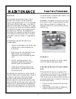
The hydraulic drive motors are extremely reliable
and will ordinarily not need maintenance or repair. If
a vibration is experienced with engine running,
check the coupler between the engine and the
hydraulic pump. Do not make this inspection while
engine is running. It will be necessary to remove the
inspection cover. After adjusting and tightening the
coupler, replace the inspection cover and then start
engine to see if the problem has been corrected. Do
not run the engine or operate the lifter with the cover
removed or not firmly attached.
CAUTION:
This breather is designed to pressurize
the reservoir to 5 PSI. Loosen cap slowly to avoid
injury whenever adding oil or working on the
hydraulic system. Use a wrench on the hex directly
under the cap.
Transmission
The hydrostatic transmission is properly adjusted
when no movement of the unit is visible.
Transmission Return to Neutral Adjust-
ment
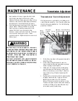
The hydrostatic transmission is equipped with a
self-centering device that centers the swash plate to
stop flow to the wheel motors, stopping the ma-
chine. If unit creeps one direction when controls are
released adjustment may be required. To adjust use
the following procedure:
1. Follow procedure in Operator Manual to Shut
Off Machine.
2. Detach throttle control cables at transmission
and jack front wheels off of ground.
Power Train/Transmission
Summary of Contents for Lift Jockey LJS2000
Page 2: ......
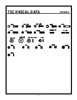
Page 13: ...13 TECHNICAL DATA Hardware...
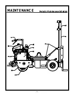
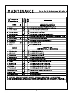
Page 34: ...34 MAINTENANCE Periodic Maintenance Schedule...
Page 35: ...35 MAINTENANCE Periodic Maintenance Schedule...
Page 38: ......
Page 40: ...40 PARTS LIST Tilt Cylinder Front Cowl Assembly...
Page 41: ...41 PARTS LIST Tilt Cylinder Front Cowl Assembly...
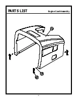
Page 42: ...42 PARTS LIST Engine Cowl Assembly...
Page 43: ...43 PARTS LIST Engine Cowl Assembly...
Page 44: ...44 PARTS LIST Engine Assembly...
Page 45: ...45 PARTS LIST Engine Assembly...
Page 46: ...46 PARTS LIST Pump Assembly...
Page 47: ...47 PARTS LIST Pump Assembly...
Page 48: ...48 PARTS LIST Battery Hose Clamp Assembly...
Page 49: ...49 PARTS LIST Battery Hose Clamp Assembly...
Page 50: ...50 PARTS LIST Steering Housing Assembly...
Page 51: ...51 PARTS LIST Steering Housing Assembly...
Page 52: ...52 PARTS LIST Hydraulic Tank Assembly...
Page 53: ...53 PARTS LIST Hydraulic Tank Assembly...
Page 54: ...54 PARTS LIST Steering Handle Bar Fuel Tank Assembly...
Page 55: ...55 PARTS LIST Steering Handle Bar Fuel Tank Assembly...
Page 56: ...56 PARTS LIST Platform Brake Pedal Assembly...
Page 57: ...57 PARTS LIST Platform Brake Pedal Assembly...
Page 58: ...58 PARTS LIST Brake Linkage Assembly...
Page 59: ...59 PARTS LIST Brake Linkage Assembly...
Page 60: ...60 PARTS LIST Wheelmotor Brake Tire Assembly...
Page 61: ...61 PARTS LIST Wheelmotor Brake Tire Assembly...
Page 62: ...62 PARTS LIST Quick Change Hub Assembly...
Page 63: ...63 PARTS LIST Quick Change Hub Assembly...
Page 64: ...64 PARTS LIST Hand Foot Mast Control Assembly...
Page 65: ...65 PARTS LIST Hand Foot Mast Control Assembly...
Page 66: ...66 PARTS LIST Mast Assembly...
Page 67: ...67 PARTS LIST Mast Assembly...
Page 68: ...68 PARTS LIST Mast Assembly...
Page 69: ...69 PARTS LIST Mast Assembly...
Page 70: ...70 PARTS LIST Lift Frame Assembly...
Page 71: ...71 PARTS LIST Lift Frame Assembly...
Page 72: ...72 PARTS LIST Hydraulic Piping Schematic...
Page 73: ...73 PARTS LIST Hydraulic Piping Schematic...
Page 74: ...74 PARTS LIST Hydraulic Piping Schematic...
Page 75: ...75 PARTS LIST Hydraulic Piping Schematic...
Page 76: ...76 PARTS LIST Hydraulic System Schematic...
Page 77: ...77 PARTS LIST Hydraulic System Schematic...
Page 78: ...78 PARTS LIST Electrical Wiring Schematic...
Page 79: ...79 PARTS LIST Electrical Wiring Schematic...
Page 80: ...80 PARTS LIST 55398 Decal Identification...
Page 82: ...82 PARTS LIST Decal Identification...
Page 84: ......
Page 85: ......
Page 86: ......

