- 30 -
MAINTENANCE
WHEN REPLACING TIRES OR
CHANGING TO DUAL WHEEL
C O N F I G U R A T I O N , U S E
MANUFACTURERS RECOMMENDED
TIRES ONLY. FAILURE TO FOLLOW
THIS WARNING COULD RESULT IN
SERIOUS INJURY OR DEATH.
Changing Single Wheel to Dual Wheel
Standard Machine
1. Jack machine. Apply parking brake.
2. Remove five (5) lug nuts.
3. Assemble inner dual wheel adapter then replace
five (5) lug nuts on adapter wheel and torque to
32 ft. lbs.
4. Assemble outer wheel.
5. Assemble five (5) lugnuts and torque to 32 ft.lbs.
6. Repeat above steps on opposite side of machine.
Quick Release Wheel Option
1. Position machine inner wheel over 2x4 and apply
parking brake.
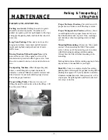
2. Remove large tee bolt in center of wheel with
crow bar (figure 7).
3. Remove outside wheel with quick-change hub
attached.
4. Repeat above steps on opposite side of machine.
Tires, Lugnuts and Hardware
- Check that all lugnuts are tight weekly using a
torque of 90 ft. lbs. (122 Nm). This is
important on new machines or newly replaced
wheels.
Figure 7
- Inspect all hardware is tight weekly (see
Torque Charts Section).
NOTE:
When installing or replacing hardware,
loctite 262 threadlocker is required to prevent
loosening.
Proper Care--
Inspect tires for cuts, slashes, or
bulges. Tires with defects need to be replaced or
repaired for proper handling and safety.
Tires, Lugnuts, Hardware/Changing
Wheel/Quick Release Wheel
WARNING
Summary of Contents for Lift Jockey LJS2000
Page 2: ......
Page 13: ...13 TECHNICAL DATA Hardware...
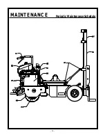
Page 34: ...34 MAINTENANCE Periodic Maintenance Schedule...
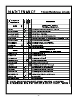
Page 35: ...35 MAINTENANCE Periodic Maintenance Schedule...
Page 38: ......
Page 40: ...40 PARTS LIST Tilt Cylinder Front Cowl Assembly...
Page 41: ...41 PARTS LIST Tilt Cylinder Front Cowl Assembly...
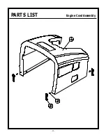
Page 42: ...42 PARTS LIST Engine Cowl Assembly...
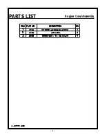
Page 43: ...43 PARTS LIST Engine Cowl Assembly...
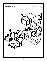
Page 44: ...44 PARTS LIST Engine Assembly...
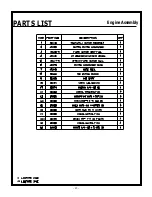
Page 45: ...45 PARTS LIST Engine Assembly...
Page 46: ...46 PARTS LIST Pump Assembly...
Page 47: ...47 PARTS LIST Pump Assembly...
Page 48: ...48 PARTS LIST Battery Hose Clamp Assembly...
Page 49: ...49 PARTS LIST Battery Hose Clamp Assembly...
Page 50: ...50 PARTS LIST Steering Housing Assembly...
Page 51: ...51 PARTS LIST Steering Housing Assembly...
Page 52: ...52 PARTS LIST Hydraulic Tank Assembly...
Page 53: ...53 PARTS LIST Hydraulic Tank Assembly...
Page 54: ...54 PARTS LIST Steering Handle Bar Fuel Tank Assembly...
Page 55: ...55 PARTS LIST Steering Handle Bar Fuel Tank Assembly...
Page 56: ...56 PARTS LIST Platform Brake Pedal Assembly...
Page 57: ...57 PARTS LIST Platform Brake Pedal Assembly...
Page 58: ...58 PARTS LIST Brake Linkage Assembly...
Page 59: ...59 PARTS LIST Brake Linkage Assembly...
Page 60: ...60 PARTS LIST Wheelmotor Brake Tire Assembly...
Page 61: ...61 PARTS LIST Wheelmotor Brake Tire Assembly...
Page 62: ...62 PARTS LIST Quick Change Hub Assembly...
Page 63: ...63 PARTS LIST Quick Change Hub Assembly...
Page 64: ...64 PARTS LIST Hand Foot Mast Control Assembly...
Page 65: ...65 PARTS LIST Hand Foot Mast Control Assembly...
Page 66: ...66 PARTS LIST Mast Assembly...
Page 67: ...67 PARTS LIST Mast Assembly...
Page 68: ...68 PARTS LIST Mast Assembly...
Page 69: ...69 PARTS LIST Mast Assembly...
Page 70: ...70 PARTS LIST Lift Frame Assembly...
Page 71: ...71 PARTS LIST Lift Frame Assembly...
Page 72: ...72 PARTS LIST Hydraulic Piping Schematic...
Page 73: ...73 PARTS LIST Hydraulic Piping Schematic...
Page 74: ...74 PARTS LIST Hydraulic Piping Schematic...
Page 75: ...75 PARTS LIST Hydraulic Piping Schematic...
Page 76: ...76 PARTS LIST Hydraulic System Schematic...
Page 77: ...77 PARTS LIST Hydraulic System Schematic...
Page 78: ...78 PARTS LIST Electrical Wiring Schematic...
Page 79: ...79 PARTS LIST Electrical Wiring Schematic...
Page 80: ...80 PARTS LIST 55398 Decal Identification...
Page 82: ...82 PARTS LIST Decal Identification...
Page 84: ......
Page 85: ......
Page 86: ......

