2400 User Manual
Copyright © 2004 Stoneridge Electronics Ltd
5
1.0 2400 SERIES TACHOGRAPH (WITH DISPLAY)
The 2400 series automatic electronic tachograph detailed within this user manual comprises an electronically controlled chart recorder
within a drawer, which in turn locates in an ISO standard radio enclosure. This enables mounting in a variety of locations, ensuring that
insertion and removal of the charts and operation of the controls can be easily achieved by the operator. The tachograph has been
designed to comply with EC Regulations and thus displays and records speed and distance in metric units (kilometres per hour and
kilometres respectively). In addition to displaying and recording the speed of the vehicle and the distance travelled, the tachograph
incorporates an electronic real time clock, which controls the mechanism that rotates the charts and indicates the current time on the
Tachograph’s display.
The tachograph charts, upon which the speed, duty and distance travelled are recorded, are circular sheets of wax-covered paper, each of
which features a pear-shaped central hole that is used to accurately locate it over the drive spindle of the electronic drive. Styli within the
tachograph bear against the charts in order to mark them with indelible ‘traces’. Normally there are three trace types representing speed,
duty and distance. However, if requested by the customer, the tachograph can be enabled to produce a fourth trace to record events such
as off-road driving or engine revolution recording.
The drawer, which contains the charts, the display and the controls, is electro-mechanically held in the locked closed position
while the vehicle is being driven, and can only be opened, (in order to facilitate access for inserting or removing charts) when the
vehicle is stationary and the ignition is switched on.
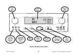
The upper right hand area of the display (the ‘odometer’) identifies the distance travelled to the nearest 1/10 km as a seven-digit figure. The
current time is displayed in the lower right hand area of the display as a four-digit figure (24-hour clock). The current speed of the vehicle is
displayed on the left-hand side of the display.
The tachograph is designed for use by up to two drivers, and thus two identical sets of driver-specific controls are provided adjacent to the
display, each of which comprise a Driver Duty push-button and three Light Emitting Diodes (LEDs) that indicate the various work modes.
Three further control push-buttons are provided on the tachograph, immediately below the display. The left-hand control is a Mode Change
push-button, the centre control is an Advance push-button and the right hand control is an Eject push-button. The controls are identified on
Figure 1 (overleaf).
1.1 2400 Tachograph With Remote Display
The 2400 series tachograph may be installed as a component of a wider system, for example an instrument cluster. The information that is
shown on the tachograph’s display, that is speed, odometer and time would thus also be displayed elsewhere on the vehicle’s instrument
cluster.


