16
Chapter 2
Planning the IPS Installation
Capture Interfaces
Sensors can be connected to a switch SPAN port or a network TAP to capture network traffic.
Hubs can be used, but are not recommended. The considerations for these connection methods
are explained below. Additionally, the IPS Sensor can be installed in-line, so that the network
traffic is routed through the Sensor, allowing active blocking of any connection.
For more specific information on compatibility of different network devices and StoneGate IPS,
refer to the Stonesoft website at
http://www.stonesoft.com/support/
Switch SPAN Ports
A
Switched Port Analyzer
(SPAN) port is used for capturing network traffic to a defined port on a
switch. This is also known as
port mirroring
. The capturing is done passively, so it does not
interfere with the traffic.
A Sensor’s capture interface can be connected directly to a SPAN port of a switch. All the traffic
to be monitored must be copied to this SPAN port.
Network TAPs
A
Test Access Port
(TAP) is a passive device located at the network wire between network
devices. The capturing is done passively, so it does not interfere with the traffic. With a network
TAP, the two directions of the network traffic is divided to separate wires. For this reason, the
Sensor needs two Capture interfaces for a network TAP; one capture interface for each direction
of the traffic. The two related Capture interfaces must have the same
Logical interface
that
combines the traffic of these two interfaces for inspection. You could also use the pair of
Capture interfaces to monitor traffic in two separate network devices.
Cabling Guidelines
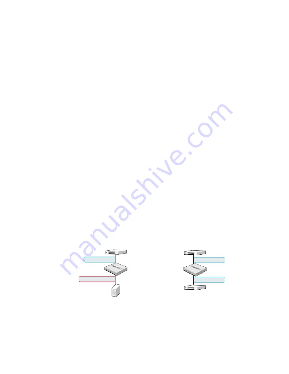
Follow standard cabling with inline IPS: use straight cables to connect the sensor to switches/
hubs and crossover cables to connect the sensor to hosts. Both crossover and straight cables
may work when the sensors are operating normally due to software-level correction, but only the
correct type of cable allows traffic to flow when fail-open network cards must pass traffic without
the help of higher-level features.
Also, make sure the cables are correctly rated (CAT 5e or CAT 6 in gigabit networks).
Illustration 2.1 Correct Cable Types
Switch/firewall
Host
Switch/firewall
Switch
Straight cable
Crossover cable
Straight cable
Straight cable
Summary of Contents for stonegate 5.2
Page 1: ...STONEGATE 5 2 INSTALLATION GUIDE INTRUSION PREVENTION SYSTEM...
Page 5: ...5 INTRODUCTION In this section Using StoneGate Documentation 7...
Page 6: ...6...
Page 12: ...12...
Page 18: ...18 Chapter 2 Planning the IPS Installation...
Page 28: ...28 Chapter 4 Configuring NAT Addresses...
Page 30: ...30...
Page 50: ...50 Chapter 6 Saving the Initial Configuration...
Page 60: ...60...
Page 72: ...72 Chapter 8 Installing the Engine on Intel Compatible Platforms...
Page 73: ...73 UPGRADING In this section Upgrading 75...
Page 74: ...74...
Page 88: ...88...


