background image

`2–8  Installing and Operating a  Pedestal  

2.10  Connecting the SCSI Bus Cables

Once you have installed all the storage devices, you can connect the SCSI bus cable.

CAUTION

Connecting the SCSI bus cable with power applied to either the controller or the
pedestal can generate erroneous signals and cause the SCSI bus to “hang.”
Always turn off the power on both the host and the pedestal when connecting or
disconnecting the SCSI cables.

The cables recommended for connecting the SCSI controller are either a BN21K or BN21L
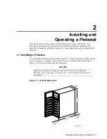
series SCSI cable.  The 68-pin, high-density connector (see Figure 2–7) connects to the SCSI
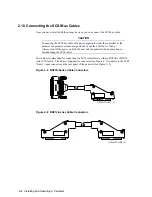
“Bus A” input connector on the rear panel of the pedestal (see Figure 2–9).


Figure 2–7  BN21K-Series Cable Connectors

CXO-4171A-MC_R


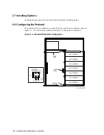
Figure 2–8  BN21L-Series Cable Connectors

CXO-4172A-MC_R

Summary of Contents for BA346-K Series

Page 1: ...d Massachusetts Solutions BA346 K Series Deskside Expansion Pedestal User s Guide Order Number EK BA346 UG A01 This guide describes the procedures for installing configuring and maintaining the BA346...

Page 2: ...operate this equipment This equipment generates uses and can radiate radio frequency energy and if not installed and used in accordance with the instructions may cause harmful interference to radio c...

Page 3: ...paring the Pedestal for Operation 2 5 2 6 Mounting the Base 2 5 2 7 Installing Options 2 6 2 8 Configuring the Pedestal 2 6 2 9 Installing SBBs 2 7 2 10 Connecting the SCSI Bus Cables 2 8 2 11 Connect...

Page 4: ...orage SBB Status LEDs 2 10 Figure 2 13 Mounting the Door 2 11 Figure 3 1 Standard Shipping Configuration 3 1 Figure 3 2 SCSI Cables and Accessories 3 2 Figure 3 3 BA346 KB SCSI Bus Lengths 3 4 Figure...

Page 5: ...l and includes Unpacking pedestals Selecting the installation area Selecting SCSI buses and cables Connecting the pedestal to the SCSI controller Installing the SBBs Chapter 3 This chapter contains th...

Page 6: ...s guide are as follows boldface type Boldface type indicates the first instance of terms being defined in the text the glossary or both italic type Italic type indicates emphasis and complete publicat...

Page 7: ...enclosure for creating a user defined storage array using the small computer system interface SCSI bus The following are the features of this pedestal Single ended 8 bit or 16 bit SCSI 2 bus Capacity...

Page 8: ...ckplane bus into two buses a four device bus and a three device bus When used in conjunction with the 5 25 inch option kit you can have a six device bus and a three device bus in the same pedestal See...

Page 9: ...ices 5 25 inch devices and 3 5 inch SBBs SCSI cables BN21K or BN21L Table 1 1 lists the major pedestal components supplied with the basic unit and each option Table 1 1 Major BA346 K Series Pedestal C...

Page 10: ...the internal dc power distribution Table 1 2 lists the power supply specifications and Table 1 3 lists the country specific ac power cords Table 1 2 Power Supply Specifications Specification Rating Po...

Page 11: ...S 546 2 5 8 2 BN19S 2E Ireland 250 V ac 10 A IEC 320 C13 C14 BS 1363 2 5 8 2 BN19A 2E Israel 250 V ac 10 A IEC 320 C13 C14 SI 32 2 5 8 2 BN18L 2E Italy 250 V ac 10 A IEC 320 C13 C14 CEI 213 16 VII 2 5...

Page 12: ...ces The power supply internal fan cools the 5 25 inch devices and the power supply As shown in Figure 1 4 both fans draw air through the front of the pedestal through the storage devices and exhaust i...

Page 13: ...pedestal compatible 3 5 inch storage devices Figure 1 5 Typical 3 5 Inch SBB CXO 4379A MC The following primary factors determine the compatible storage devices The SCSI controller must support all t...

Page 14: ...minimum Power available to 5 25 inch devices 5 V dc 20 A 12 V dc 8 A Table 1 5 lists the air flow through the pedestal under test conditions with the door open Table 1 5 Air Flow Device Qty Slots Meas...

Page 15: ...talling a Pedestal You can usually install the pedestal within 2 meters 6 6 feet of the SCSI controller and next to an ac receptacle A desktop a table or the floor are acceptable installation location...

Page 16: ...estal and all components Digital recommends that you unpack the pedestal in the installation WARNING To prevent personal injury always use two people to pack unpack or move the pedestal in the shippin...

Page 17: ...Installing and Operating a Pedestal 2 3 Figure 2 2 Pedestal Packing SHIPPING CARTON USER DOCUMENTATION FOAM BLOCK BA346 KB DOOR WITH SHIPPING SLEEVE CXO 4633A MC...

Page 18: ...mponents in the plastic bags 2 Remove the packing material from the shipping container 3 Open the shipping container and orient it as shown in Figure 2 2 4 Remove the door and all external cables from...

Page 19: ...the power and SCSI bus cables Checking the pedestal and its components for proper operation Mounting the door 2 6 Mounting the Base Complete the following procedure to mount the base BA35X VB option...

Page 20: ...figured as a single SCSI bus with the device addresses shown in Figure 2 4 You can use the procedures in Chapter 3 to change the configuration Figure 2 4 Standard BA346 KB Configuration CXO 4550A MC J...

Page 21: ...s shelf slots and backplane connectors preclude installing an SBB incorrectly you can insert an SBB only one way Each 3 5 inch SBB occupies one shelf slot When you insert an SBB into a shelf and fully...

Page 22: ...cause the SCSI bus to hang Always turn off the power on both the host and the pedestal when connecting or disconnecting the SCSI cables The cables recommended for connecting the SCSI controller are ei...

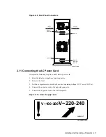
Page 23: ...d Complete the following steps to connect the ac power cord 1 Read the label covering the ac input connector 2 Remove the label 3 Set the ac input selector switch to the correct operating voltage 115...

Page 24: ...a detailed description of the SBB status LEDs please refer to the SBB User s Guide The individual 5 25 inch device users guides describes the function and purpose of the status LEDs Figure 2 11 Pedest...

Page 25: ...rating you can install the door to provide security for the storage devices A locked door precludes removing storage devices Figure 2 13 shows how to mount the door by inserting the hinge pins on the...

Page 26: ...esult in corrupted or lost data if the controller does not support hot swap Warm swap This method requires a that the SCSI controller makes one bus inactive quiescent while the other buses remain acti...

Page 27: ...installation procedures The standard configuration shown in Figure 3 1 and described in and is factory installed Figure 3 1 Standard Shipping Configuration CXO 4550A MC J10 INPUT CABLE J11 J16 J17 JU...

Page 28: ...a description of each configuration As shown in Table 3 2 and Figure 3 2 the SCSI bus accessories include a terminator and cables Table 3 2 SCSI Bus Accessories Quantity per Model Item BA346 KB Stand...

Page 29: ...e Bus Length Recommended Cable Width Type Controller Termination MT s MB s Meters Feet Order Number Meters Feet 8 bit Fast Differential 10 10 25 82 BN21K 23 BN21L 23 23 82 8 bit Fast Single ended 10 1...

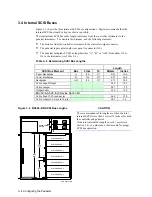
Page 30: ...g SCSI Bus Lengths Length SCSI Bus Element Bus From To Meters Inches Upper Backplane A J10 J11 0 41 16 0 Lower Backplane B J16 J17 0 25 10 0 Backplane AB J10 J17 0 73 28 8 Cable Input Output 0 30 12 0...

Page 31: ...onnect the pedestal power cord 3 Disconnect the external SCSI bus cables 4 Remove the front door by lifting it up and off the bezel 5 Remove the left side cover screws see Figure 3 4 6 Grasp the side...

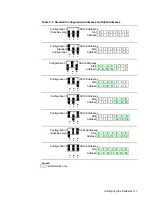
Page 32: ...ddress configurations Figure 3 6 shows the location of connector J18 and the jumpers Table 3 5 defines the slot addresses assigned for each of the eight address configurations Figure 3 7 shows the sta...

Page 33: ...lot 0 1 2 3 4 5 6 Address 8 9 10 11 0 1 2 W 1 W 2 W 3 Configuration 4 SCSI Addresses Slot 0 1 2 3 4 5 6 Address 8 9 10 11 4 5 6 W 1 W 2 W 3 Configuration 5 SCSI Addresses Slot 0 1 2 3 4 5 6 Address 0...

Page 34: ...bit removable media SBB with an address switch refer to the SBB User s Guide To use the slot address set the device address switch to the default setting Duplicate device addresses on a single 8 bit S...

Page 35: ...evice being removed or reinstalled is the only device that cannot perform operations during this process See also cold swap and warm swap megabytes per second MB s See megatransfers per second megatra...

Page 36: ...buses a four device bus and a three device bus creates a split bus spin down Removing power and halting data transfer starts the spin down process When the device is no longer rotating and you can mov...

Page 37: ...Glossary 3 word This term indicates the size of a data construct The bus width determines the number of bytes in a word for example Bus Width Word Length 8 bit 1 byte 16 bit 2 bytes 32 bit 4 bytes...

Page 38: ......
Page 39: ...2 8 SCSI bus BN21L 2 8 SCSI bus input output 3 1 SCSI bus jumper 3 1 CAUTIONs 1 6 2 1 2 2 2 4 2 8 2 12 3 8 Cold swap 2 12 Configuration address jumpers 3 6 Configuring 2 5 2 6 Connector 68 pin 2 8 hi...

Page 40: ...termination 3 3 device address jumpers 3 8 device address switches 3 8 device addresses 2 6 2 7 3 8 differential 3 3 fast 3 3 inactive 2 12 input output cables 3 1 internal 3 4 internal bus A 3 4 int...

Reviews: