Configuring the Pedestal 3–1
3
Configuring the Pedestal
This chapter describes the standard BA346–KB pedestal configuration and how to change it.
3.1 The Standard Configuration
You can install the dual bus and the 5.25-inch device option at any time. Installing either
option requires changing the pedestal configuration. Digital recommends that you install the
options during the initial installation. See the individual option installation guides for
detailed option installation procedures.
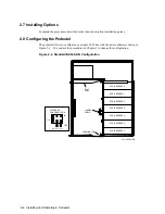
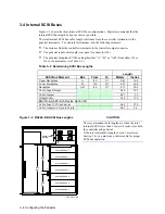
The standard configuration shown in Figure 3–1 and described in and is factory-installed.
Figure 3–1 Standard (Shipping) Configuration
CXO-4550A-MC
J10
INPUT
CABLE
J11
J16
J17
JUMPER
CABLE
TERMINATOR
STANDARD
CONFIGURATION
J18
IN
OUT
W1 W2 W3
SCSI ADDRESS 0
SCSI ADDRESS 1
SCSI ADDRESS 2
SCSI ADDRESS 3
SCSI ADDRESS 4
SCSI ADDRESS 5
SCSI ADDRESS 6
Table 3–1 Standard Configuration Specifications
Backplane Bus Type
Single
Device Addresses
8-bit devices:
0-6
16-bit devices:
0-6
5.25-inch devices:
None
SCSI Bus
Cables and Terminators:
•
Input Cable (Rear panel to J10)
•
Jumper Cable (J11 to J16)
•
Terminator (J17)
Internal SCSI Bus Length
0.97 meters (38 in)
Summary of Contents for BA346-K Series
Page 38: ......

