iv
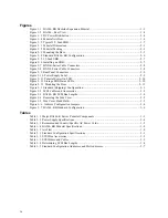
Figures
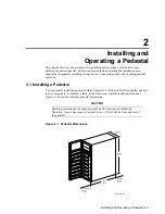
Figure 1–1 BA346–KB Deskside Expansion Pedestal...................................................................... 1–1
Figure 1–2 BA346 – Rear View ...................................................................................................... 1–4
Figure 1–3 DC Power Distribution .................................................................................................. 1–4
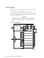
Figure 1–4 Pedestal Air Flow.......................................................................................................... 1–6
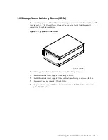
Figure 1–5 Typical 3.5–Inch SBB ................................................................................................... 1–7
Figure 2–1 Pedestal Dimensions ..................................................................................................... 2–1
Figure 2–2 Pedestal Packing ........................................................................................................... 2–3
Figure 2–3 Mounting the Base ........................................................................................................ 2–5
Figure 2–4 Standard BA346–KB Configuration .............................................................................. 2–6
Figure 2–5 3.5-Inch SBB ................................................................................................................ 2–7
Figure 2–6 Installing an SBB .......................................................................................................... 2–7
Figure 2–7 BN21K-Series Cable Connectors................................................................................... 2–8
Figure 2–8 BN21L-Series Cable Connectors ................................................................................... 2–8
Figure 2–9 Rear Panel Connectors .................................................................................................. 2–9
Figure 2–10 Power Supply Label..................................................................................................... 2–9
Figure 2–11 Pedestal Power On LED ............................................................................................ 2–10
Figure 2–12 Storage SBB Status LEDs.......................................................................................... 2–10
Figure 2–13 Mounting the Door.................................................................................................... 2–11
Figure 3–1 Standard (Shipping) Configuration ............................................................................... 3–1
Figure 3–2 SCSI Cables and Accessories......................................................................................... 3–2
Figure 3–3 BA346–KB SCSI Bus Lengths ...................................................................................... 3–4
Figure 3–4 Removing the Side Cover .............................................................................................. 3–5
Figure 3–5 Side Cover Hand Hold................................................................................................... 3–5
Figure 3–6 Address Configuration Jumpers.................................................................................... 3–6
Figure 3–7 BA346–KB Standard Configuration .............................................................................. 3–6
Tables
Table 1–1 Major BA346–K Series Pedestal Components................................................................ 1–3
Table 1–2 Power Supply Specifications........................................................................................... 1–4
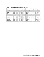
Table 1–3 Recommended Country-Specific AC Power Cords.......................................................... 1–5
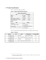
Table 1–4 BA346–KB Pedestal Specifications................................................................................. 1–8
Table 1–5 Air Flow......................................................................................................................... 1–8
Table 3–1 Standard Configuration Specifications............................................................................ 3–1
Table 3–2 SCSI Bus Accessories..................................................................................................... 3–2
Table 3–3 SCSI Buses and Cables................................................................................................... 3–3
Table 3–4 Determining SCSI Bus Lengths ...................................................................................... 3–4
Table 3–5 Standard Configuration Addresses and Slot Addresses.................................................... 3–7
Summary of Contents for BA346-K Series
Page 38: ......


