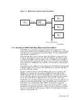
Figure 1–2 HSD05 Array Controller Typical Installation
HOST
SYSTEM
DSSI BUS
SCSI BUS
HSD05
ARRAY
CONTROLLER
SCSI
DEVICE
UP TO 7 SCSI DEVICES
CXO-4005B-MC
SCSI
DEVICE
SCSI
DEVICE
1.1.2 Overview of HSD05 Operating Requirements/Limitations
The HSD05 array controller is designed for installation in shelf slot 0. This
preserves the integrity of the backplane SCSI bus, as the HSD05 array controller
normally serves as a terminating end of the SCSI bus. Its factory-default SCSI
node address, or SCSI ID, is 7.
While attached drives may be removed when the SCSI bus is quiesced (warm-
swapped), they should not be removed with the SCSI bus active (hot-swapped)
to avoid the possibility of data corruption errors. The HSD05 array controller
itself should only be removed when the power is off to all nodes on the DSSI bus
that is attached to the HSD05 array controller, and shelf power is disconnected
(cold-swap).
Depending upon the complexity of the configuration, total DSSI bus length should
be limited to between 30 to 60 feet with an HSD05 array controller attached to
guarantee DSSI bus integrity.
Though it comprises the low end of the HSD family of array controllers, the
HSD05 array controller does not support DIGITAL Standard Disk Format
(DSDF™) protocol. Drives written by the HSD05 array controller can only be
read by other StorageWorks array controllers using Transportable mode format;
refer to the documentation supplied by other units on the use of this mode.
The HSD05 array controller supports host-based volume shadowing, but does not
support controller-based shadowing assists. No HSD05 array controller-based
Redundant Array of Independent Disks (RAID) functionality is supported.
The HSD05 array controller identifies attached disk devices as RF72 or RA82
disk drives, and attached tape devices as TU81 tape drives. This does not affect
the actual accessible device storage space. However, the following restrictions
apply to creating shadow sets:
Introduction 1–3


