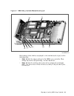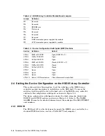
Table 2–2 HSD05 Array Controller Module Board Jumpers
Jumper
Definition
W1
Reserved
W2
Reserved
W3
EPROM size
W4
Wait state
W5
Reserved
W6
Reserved
W7
Reserved
W8
DSSI terminator power supplied by module
W9
SCSI terminator power supplied by module
Table 2–3 Device Configuration Switchpack (SW2) Sections
Section
Definition
Default
SW2–1
MSB of DSSI ID
Open (DSSI ID = 0)
SW2–2
NSB of DSSI ID
Open
SW2–3
LSB of DSSI ID
Open
SW2–4
MSB of SCSI ID
Closed (SCSI ID = 7)
SW2–5
NSB of SCSI ID
Closed
SW2–6
LSB of SCSI ID
Closed
SW2–7
Spare
Open
SW2–8
Spare
Open
SW2–9
Spare
Open
SW2–10
Active SCSI termination
Closed (terminators installed)
2.4 Setting the Device Configuration on the HSD05 Array Controller
This section contains the procedure to set the switches on the HSD05 array
controller module board prior to installation in the SBB shelf. To access the
switches, look through the slot in the back cover of the HSD05 array controller
and locate the configuration switchpack, as shown in Figure 2–2.
The device configuration switchpack contains 10 switch elements, divided into
DSSI ID and SCSI ID sections as shown in Figure 2–2. Refer to The NAME_
ALGRM Parameter for detailed information on the makeup of the MSCP/TMSCP
unit numbers.
2.4.1 DSSI ID
The DSSI port (J1) on the front panel connects the HSD05 array controller to a
standard DSSI bus device, such as a VAX 4000™ host computer.
2–4 Preparing to Use the HSD05 Array Controller


