background image

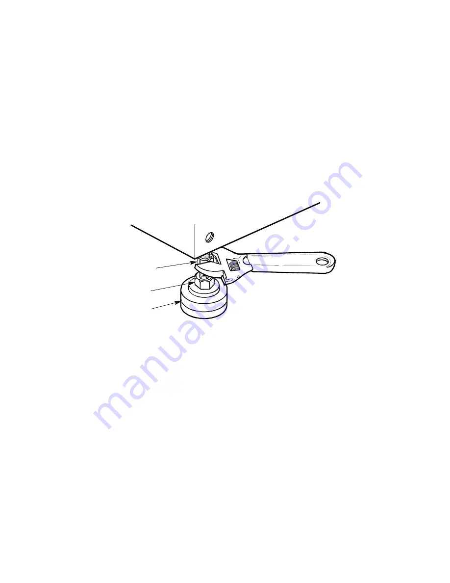
3.5 Leveling the Cabinet

Level the cabinet in its final position as follows:
1. Loosen the locknuts on all four leveler feet as shown in Figure 3–5.
2. Turn each leveler hex nut clockwise until the leveler foot contacts the floor.
3. Adjust all four leveler feet until the cabinet is level and the load is removed

from all casters. Verify that the casters spin freely.

4. Tighten the locknuts on all four leveler feet.

Figure 3–5 Leveler Foot Adjustment

LOCKNUT

LEVELER
HEX NUT

LEVELER
FOOT

CXO-3829A

3.6 Installing the Skirt Kit

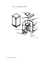
The skirt kit is packaged separately inside the corrugated carton with the

cabinet. Installation of the skirt kit is optional. Install the skirt kit around the

base of the cabinet as follows:
1. Unpack the skirt kit carton and use Figure 3–6 to identify the right, left,

front, and rear skirts.

2. Position the skirts next to the cabinet, as shown in Figure 3–6.
3. The fasteners on the skirts consist of small pins with flat and barbed sides.

Using a Phillips screwdriver, turn the fasteners on each skirt until the flat

sides face up.

4. Position each skirt such that the fasteners mate with the receptacles on the

cabinet’s base.

5. Using a Phillips screwdriver, push each fastener straight into its mating

receptacle on the cabinet base.
(With the fasteners locked in place, a small amount of play allows the skirts

to be adjusted slightly up or down for proper alignment.)

Unpacking and Installation 3–7

Summary of Contents for SH043 Series

Page 1: ...cedures necessary to install configure and use StorageWorks SH043 series cabinets Both mechanical cabinet configuration and power configuration are covered in this manual The configuration and connect...

Page 2: ...d States of America NOTE This equipment generates uses and may emit radio frequency energy The equipment has been type tested and found to comply with the limits for a Class A digital device persuant...

Page 3: ...abinet 3 1 3 2 Removing the Cabinet from the Pallet 3 3 3 3 Configuring the Cabinet Rack Space 3 6 3 4 Placing the Cabinet 3 6 3 5 Leveling the Cabinet 3 7 3 6 Installing the Skirt Kit 3 7 3 7 Inspect...

Page 4: ...he Front Air Separation Panel 6 7 6 5 2 Installing the Rear Air Separation Panel 6 7 6 6 Reinstalling Exterior Cabinet Panels 6 9 7 Installing TZLX Series Tape Drives 7 1 General Installation Consider...

Page 5: ...cations 4 3 5 1 SH043 Controller Storage Cabinet Shelf Locations 5 2 5 2 SH043 Controller Storage Cabinet Shelf and Tape Drive Locations 5 3 6 1 Exterior Cabinet Panel Removal and Installation 6 2 6 2...

Page 6: ...iv 4 Schallemissionswerte Vorl ufige Werteangaben nach ISO 9296 und ISO 7779 DIN EN27779 xv 1 1 SH043 Series Cabinet Specifications 1 3 5 1 SH043 Controller Storage Cabinet SCSI 2 Cable Lengths 5 5 6...

Page 7: ...by qualified service personnel Model Numbers Some equipment model numbers used in this manual are equivalent to those of other StorageWorks equipment Table 1 contains equivalent StorageWorks model num...

Page 8: ...fines the acronyms and specialized terms used in this document Index The Index provides a cross reference to subject matter in this document Related Documents Table 2 lists the StorageWorks related us...

Page 9: ...3 UG StorageWorks Metric Shelf Bracket Kit Installation Guide EK 35XRD IG StorageWorks RETMA Shelf Rail Kit Installation Guide EK 35XRB IG StorageWorks SH043 Series Cabinet Installation and User s Gui...

Page 10: ...n Sheet EK RZ2XD UG SCSI Signal Converter DWZZA AA EK DWZZA SV SCSI Signal Converter DWZZA MA EK DWZZM SV SCSI Signal Converter DWZZA VA EK DWZAA SV TLZ06 Cassette Tape Drive Installation Guide EK STE...

Page 11: ...his manual boldface type Boldface type indicates the first instance of terms being defined in text in the glossary or both italic type Italic type indicates emphasis and complete manual titles In the...

Page 12: ......

Page 13: ...Benutzer f r entsprechende Gegenma nahmen verantwortlich sind ATTENTION Ceci est un produit de Classe A Dans un environment domestique ce produit risque de cr er des interf rences radi lectriques il...

Page 14: ...lves each containing 2 HSJ40 controllers and 8 SHDZZ ZZ shelves each containing 6 SHZBZ ZZ disk drives 7 0 7 0 50 0 51 0 Per device when installed in SH043 SHDZZ ZZ shelf containing 6 SHZBZ ZZ disk dr...

Page 15: ...6 SHZBZ ZZ disk drives 5 7 5 7 39 39 BA350 MA shelf mit 2 HSJ40 controllers 5 6 5 6 39 39 Schalleistungspegel B Schalldruckpegel dBA Bediener Position Ger t Leerlauf Betrieb Leerlauf Betrieb nur SH04...

Page 16: ......

Page 17: ...accommodate both data storage and controller data storage combinations The cabinet and its StorageWorks shelves can be configured with dual ac power capability for power redundancy SH043 series cabine...

Page 18: ...Figure 1 1 SH043 Series Cabinet CXO 3897A MC 1 2 Introduction...

Page 19: ...1 8 C for each 1000 m altitude 1 0 F for each 1000 ft altitude Humidity 10 to 85 percent at maximum wet bulb temperature of 32 C 90 F and minimum dew point of 2 C 36 F Recommended Environmental Limit...

Page 20: ...The shelves are 445 mm 17 5 inch in width and are designed to slide into the shelf brackets SBBs StorageWorks building blocks SBBs are modular computer peripheral devices or power units from the Stor...

Page 21: ...Figure 1 2 Cabinet Major Components SBB SHELF SHELF BRACKET SBB CONTROLLER SHELF CDU INSTALLED IN REAR CXO 3896A MC CABINET Introduction 1 5...

Page 22: ...s can be installed in the upper area of the cabinet as shown in Figure 1 3 A chassis rail is used to support the tape drive from one side Figure 1 3 TZLX Series Tape Drive CXO 3954A MC CABINET CHASSIS...

Page 23: ...description of each configuration option follows 1 3 1 Single Cabinet Power Configuration In the single cabinet power configuration shown in Figure 1 4 a single ac power source and CDU A are used to...

Page 24: ...e shelf remains powered by the other supply This configuration provides shelf power supply redundancy to the shelf s peripheral devices The cabinet supports a maximum of six shelves in the dual shelf...

Page 25: ...mary power source CDU A or ac power supply A fails the shelf remains powered by ac power supply B This configuration provides complete power redundancy to the shelf s peripheral devices Figure 1 6 Dua...

Page 26: ...tatus of the shelf blowers to be monitored by the host system Filler panels and air separation panels are used to properly route heated air through the cabinet Filler panels are flat plates that serve...

Page 27: ...tacles are the correct versions for the power plugs provided with the cabinet The SH043 ZZ cabinet is supplied with a power cable that has an IEC 309 plug The site floor can safely bear the weight of...

Page 28: ...nected to other equipment by one or more interface buses For both safety and reliable operation proper grounding is required between the cabinet and other equipment WARNING If enclosures are not conne...

Page 29: ...following areas should be investigated Do all outlets have power ground connections Do the power cables on all equipment at the site have grounding prongs Are all power outlet neutral connections isol...

Page 30: ......

Page 31: ...when the unit is turned on Environmental stabilization begins when the equipment is placed in the room in which it is to be installed 1 Remove the cover the fasteners and the corrugated board from th...

Page 32: ...ontainer Contents COVER FASTENERS SHIPPING STRAPS CARTON CONTAINING UNLOADING RAMPS MANUALS PALLET PLASTIC OR BARRIER BAG FASTENERS CORRUGATED BOARD CARTON CONTAINING SKIRT KIT CXO 3533A TI 3 2 Unpack...

Page 33: ...the thickness of the ramp and greater than 50 percent of the ramp width Loose missing or broken ramp side rails Loose missing or bent metal hardware If any of these defects exist do not use the ramp...

Page 34: ...Figure 3 2 Shipping Pallet Ramp Installation CXO 688D_S SHIPPING PALLET RIGHT RAMP ATTACHES HERE RIGHT UNLOADING RAMP EXTEND RAMP TO FULL LENGTH LEFT UNLOADING RAMP 3 4 Unpacking and Installation...

Page 35: ...jury as a result of the cabinet tipping off the pallet or ramp 7 Loosen the leveler locking nuts and screw the four cabinet levelers all the way up into the cabinet WARNING Three people are required t...

Page 36: ...led information and procedures regarding shelf bracket and shelf installation 3 4 Placing the Cabinet WARNING Use extreme caution when rolling the cabinet across the floor Failure to raise all leveler...

Page 37: ...Installation of the skirt kit is optional Install the skirt kit around the base of the cabinet as follows 1 Unpack the skirt kit carton and use Figure 3 6 to identify the right left front and rear sk...

Page 38: ...that the cabinet is level 3 Make sure that there are no obstructions to the airflow from the shelf blowers The side panels may need to be removed to check the shelf blowers 4 Check the identification...

Page 39: ...indicators on each shelf power supply SBB are illuminated Refer to the StorageWorks Family User s Guide for further information on shelf status indicators WARNING Failure to reduce the leakage current...

Page 40: ......

Page 41: ...in down all disk drives and halt all tape drives in the cabinet Switch the circuit breaker on the front panel of the cabinet s cable distribution units CDUs to the OFF position 4 1 Cabinet Configurati...

Page 42: ...S1 STORAGE POSITION S2 STORAGE POSITION S3 HOLE 2 HOLE 20 HOLE 26 HOLE 32 HOLE 14 HOLE 8 FRONT TO REAR SCSI 2 CABLE ROUTING POINTS HOLE 7 CDU A CDU B 4 1 2 TZLX Series Tape Drive Shelf Locations Figu...

Page 43: ...and in accordance with the following guidelines Filler panels can be installed in empty shelf positions to control air flow and electromagnetic emissions and for the purpose of cosmetics Filler panel...

Page 44: ...of each rear shelf along the rail SCSI 2 cables destined for front shelves are routed along the base pan and up the right hand vertical cabinet rail to a point just above the CDUs refer to Figures 4 1...

Page 45: ...ghtly against the metal edges of the cabinet Signal cable bundling along the outside of the cabinet rails should be done to allow the doors to easily close Cables should be fastened along cabinet rail...

Page 46: ......

Page 47: ...ers and their installation WARNING While working in the cabinet interior ac power must be removed from cabinet components Failure to do so may result in personnel injury as a result of electric shock...

Page 48: ...ket screw See Chapter 6 for detailed procedures pertaining to the mounting of StorageWorks shelves Note The SHxzz zz controller storage shelf consists of a controller shelf with an attached storage sh...

Page 49: ...s on each side Note The SHxzz zz controller storage shelf consists of a controller shelf with an attached storage shelf In systems using SHxzz zz shelves and TZLX series tape drives storage positions...

Page 50: ...r separation panels are supplied with each cabinet Install an air separation panel just above the upper most shelf in each side of the cabinet Air separation panels are not required above TZLX series...

Page 51: ...other SCSI 2 cables connecting front shelves to rear shelves pass to the rear of the cabinet via the opening between the right hand shelf brackets at positions S4 and S9 refer to Figure 5 1 They pass...

Page 52: ...and installed with the following rules in mind WARNING Cabinet rail edges may be sharp and can slice or abrade skin or cable insulation Cables should be routed in a manner that allows the shortest ove...

Page 53: ...nce from the cabinet doors The same shelf bracket and stop bracket parts are used to mount all types of StorageWorks shelves in all locations The bracket set for shelves mounted in various positions i...

Page 54: ...counterclockwise with a 5 32 inch hex wrench 6 2 1 Removing the Exterior Cabinet Panels As shown in Figure 6 1 there are two side panel hanger clips on each side of the cabinet A matching set of hang...

Page 55: ...le insulation Note Two small ESD grounding posts are provided with the cabinet One is located on a front vertical cabinet rail and one on a rear rail Should an ESD grounding post interfere with the in...

Page 56: ...ackets until it contacts the inner stop brackets The shelf should slide smoothly into the brackets If it binds remove it and check the alignment of the shelf brackets The shelf bracket mounting screws...

Page 57: ...768A MC SHELF MOUNTING BRACKET LEFT FRONT POSITION STOP BRACKET FRONT VERTICAL CABINET RAIL STOP POSITION 1 STOP POSITION 2 STOP POSITION 3 STOP POSITION 4 STOP POSITION 5 FRONT SHELF LOCKING BRACKET...

Page 58: ...tion Filler panels are attached to the cabinet with four screws and U nuts Install a filler panel in an unused shelf location as follows Place the filler panel against the cabinet rails in the shelf p...

Page 59: ...st behind the front vertical cabinet rails as shown Position the panel as closely as possible to the top of the upper most front cabinet shelf 3 Fasten the air separation panel to the front vertical c...

Page 60: ...ls as shown in Figure 6 6 2 Position the air separation panel against the front panel of CDU A or the four U nuts as shown in either Figure 6 5 or 6 6 respectively 3 Fasten the air separation panel al...

Page 61: ...the entire surface of the side panel rests firmly against the side of the cabinet 3 Allow the panel to slide downward catching the two hanger clips as it moves 4 Install the side panel bolts into the...

Page 62: ...catch your fingers between the cabinet and the top panel when snapping the panel to the cabinet 9 Lower the cover onto the cabinet and press it down ensuring that the pins snap into the top panel fas...

Page 63: ...ting positions Only the orientation of the hardware differs between the two mounting positions There is no mechanical connection between two tape drives mounted side by side in the cabinet In situatio...

Page 64: ...oving cabinet side panels To route the cabling in configurations where access to the interior of the cabinet is limited however cabinet side panels may need to be removed Sections 7 2 1 and 7 8 presen...

Page 65: ...anel Remove the side panels as follows Figure 7 2 Cabinet Side Panel Removal and Installation LOWER SIDE PANEL HANGER CLIP SIDE PANEL TOP COVER M6x40mm BOLT 4 PLACES CXO 3899A MC SIDE PANEL HANGER CLI...

Page 66: ...mponent assembly and installation procedures for both left and right tape drive mounting positions are presented in Sections 7 3 1 7 3 2 and 7 3 3 Note Two small ESD grounding posts are provided with...

Page 67: ...n within the cabinet as follows see Figure 7 4 WARNING Cabinet rail edges may be sharp and can slice or abrade skin or cable insulation 1 Turn the cabinet power off as described in Section 7 1 2 Deter...

Page 68: ...D STANDOFF 2 PLACES REAR CHASSIS RAIL LOCATING HOLE REAR VERTICAL CABINET RAIL U NUT 10 32 4 PLACES CXO 3924A MC U NUT 10 32 2 PLACES INNER FLANGE WARNING Use care in supporting the chassis rail assem...

Page 69: ...marked in step 6 8 Reposition the chassis rail assembly as directed in steps 3 through 5 9 Fasten the chassis rail to the inner flanges of the front and rear vertical cabinet rails with four screws a...

Page 70: ...BINET RAIL INNER FLANGE OUTER FLANGE FRONT CHASSIS RAIL LOCATING HOLE CXO 3923A MC REAR VERTICAL CABINET RAIL ROUND STANDOFF 2 PLACES RAIL BRACKET WASHER LOCK 10 32 INTERNAL 6 PLACES SCREW 10 32 HEX C...

Page 71: ...hrough 5 9 Fasten the chassis rail assembly to the inner flanges of the front and rear vertical cabinet rails with four screws as shown 10 Fasten the rail bracket to the rear vertical cabinet rail wit...

Page 72: ...EF LOCK DOWN BRACKET 01 SCREW 10 32 HEX CAP 4 PLACES WASHER 10 32 LOCK 4 PLACES TAPE DRIVE ENCLOSURE FRONT WASHER 10 32 LOCK 2 PLACES SCREW 10 32 HEX CAP 4 PLACES LOCK DOWN BRACKET 02 WASHER 10 32 FLA...

Page 73: ...OCK 2 PLACES NOTE TAPE DRIVE INTERNAL COMPONENTS NOT SHOWN FOR CLARITY WARNING Use two persons to lift the TZLX series tape drive The unit is heavy and awkward to lift Failure to use two persons to li...

Page 74: ...t vertical chassis rail with two hex cap screws as shown in Figure 7 6 or 7 7 7 5 Installing the Power Cord AC power for the TZLX series tape drive is obtained from CDU A Connect the female end of the...

Page 75: ...talling the Cabinet Door Tape Bezel Kit To allow operator access to the TZLX tape drive the front cabinet door tape bezel kit must be installed To install the tape bezel kit see the Instructions for I...

Page 76: ...nel 6 Locate the four inset nylon snap fasteners on the top cabinet rails WARNING The top cover is heavy and awkward to lift Installing it is a two person task Failure to use sufficient personnel may...

Page 77: ...n the front panel of the cabinet s cable distribution units CDUs to the OFF position 8 2 Cable Distribution Units The 887 E CDU is used with SH043 series cabinets and is designed for both 230 volt 50...

Page 78: ...onfiguration Unless options are specified SH043 series cabinets are shipped with a single CDU and single shelf power supplies For ease of upgrade the cabinet is supplied with 10 black and 10 gray prei...

Page 79: ...U CDU B is installed immediately above CDU A in the rear of the cabinet Refer to the StorageWorks SH043 Series Data Center Cabinet Cable Distribution Unit Installation Guide for procedures pertaining...

Page 80: ......

Page 81: ...minutes 0 to 9 32 to 49 1 hour 10 to 1 14 to 31 2 hours 20 to 11 4 to 13 3 hours 30 to 21 22 to 5 4 hours 40 to 31 40 to 21 5 hours CAUTION Always stabilize storage devices in the operating environmen...

Page 82: ......

Page 83: ...f the SH043 series cabinet including the exterior panels and the doors This term may also be used to refer to an enclosure configured with internal storage components cable distribution unit See CDU C...

Page 84: ...d installed in a 3 inch or 5 inch carrier Typical SBBs are disk drives tape drives optical storage devices and CD ROMs SBB shelf A StorageWorks shelf such as the SHDZZ ZZ designed to house plug in SBB...

Page 85: ...and configure their own storage subsystems StorageWorks products consist of modular storage and power components and the enclosures necessary to house them Storage devices and array controllers can be...

Page 86: ......

Page 87: ...ion of SH043 cabinet 1 1 Door locks 6 2 E Environmental stabilization A 1 Exterior panels reinstalling 6 9 7 14 removal 6 2 F Filler panels 1 10 6 1 in SH043 controller storage cabinets 5 4 in SH043 s...

Page 88: ...shelf locations in 4 1 4 2 signal cable routing in 4 4 TZLX series tape drive locations in 4 2 Shelf locations in SH043 controller storage cabinets 5 1 5 3 in SH043 storage only cabinets 4 1 4 2 Shelf...

Reviews: