StorageWorks DLT 10/20 GB Cartridge Tape Drive
2–2
Order Number: EK–SM1TB–UG. E01
2.3
Preinstallation Procedures
Perform the following procedure before installing the 10/20-GB DLT Cartridge Tape Drive.
2.3.1 Setting the SCSI ID Address of the Tape Drive
The pedestal slots are numbered 0 through 7, from top to bottom, with the power supply oc-
cupying slot 7. The SCSI address switches on the rear of the SWXTL-BA SBB Tape Drive
(refer to Figure 2–1) are preset at the factory to automatic — SW-1, SW-2, and SW-3 set off
(to left); SW-4, SW-5, and SW-6 set on (to right). This setting means that the SBB tape drive
will have the address of whichever physical slot is connected. Because of the low position of
the unit’s backplane interface connector, this physical connection will be to the lower of the
three slots occupied by that unit. Physically, this means it will be one of slots 2 through 6, as
applicable. If you want a different specific logical address for any reason (i.e., if you wish to
use SCSI ID 0 or 6, or any specific value in between, regardless of physical location of the
unit), you can set the tape drive to any desired logical address by manually changing the set-
tings of switches SW-1, SW-2, and SW-3 on the SCSI switch pack, as delineated in Table 2–
1, before inserting the SBB into the pedestal.
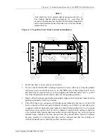
Figure 2–1 SWXTL-BA Tape Drive SCSI ID Switches

