StorageWorks DLT 10/20-GB Cartridge Tape Drive
Order Number: EK–SM1TB–UG. E01
3–3
3.4
Installation of SWXTL-BT Tabletop DLT Tape Drive
The SWXTL-BT Tabletop DLT Tape Drive is an independent unit that requires a shelf space
measuring at least 9-1/4” wide by 13” deep (plus cable connection space). Connect the tape
drive to an appropriate power source, using the supplied power cable, as follows:
1. Plug the female end of the power cord into the power jack at the rear face of the tape
drive unit and then plug the other end of that cord into an appropriate power source,
providing 120/240 Vac at 50/60 Hz.
2. Perform the POST test described in the following subsection to verify the operational in-
tegrity of the drive.
3.4.1 SWXTL-BT Power-On Self-Test (POST)
The POST test verifies operational integrity of the tape drive. The first time that you run this
test, the SWXTL-BT tape drive unit should be disconnected from the host computer, with no
tape cartridge in the drive. Once you have confirmed that the tape drive is operational, you
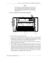
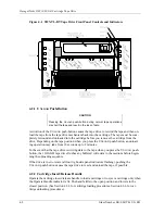
can run the POST checkout with the host system connected, as desired. Refer to Figure 3-1
for the locations of the front panel LED indicators on the drive.
To execute the power-on self-test, proceed as follows:
NOTE 1
The description of indicator sequence described in the following
procedure describes what happens when the 10/20-GB tape drive
is connected to an active SCSI bus. If the SCSI bus is not con-
nected, all left-side panel indicators remain on at all times that
power is applied to the unit.
NOTE 2
If the W
RITE
-P
ROTECTED
indicator flashes orange and the T
APE IN
U
SE
indicator flashes yellow continuously for more than 30 sec-
onds in the following test, then the POST test has failed. Repeat
the test to clear the failure (power off and then on). If the test still
fails, replace the drive.
1. Ensure that there is no cassette tape in the drive.
2. Power on the tape drive (depress top “1” portion of 1/0 rocker switch on rear panel) and
observe that all left-side panel indicators initially light, with all right-side indicators then
lighting sequentially, from top to bottom.
3. If the SCSI bus is not connected, all left-side panel indicators will stay lit; if the SCSI
bus is connected, all left-side panel indicators should go out within 1 second after power
is applied, while all right-side panel indicators should remain lighted for 3 to 5 seconds
and then go out, except for T
APE IN
U
SE
indicator, which continues to blink for a few
seconds while tape mechanism searches for tape and then goes out. When the T
APE IN
U
SE
indicator goes out, an internal beeper sounds to alert the operator and the green
O
PERATE
H
ANDLE
indicator becomes steadily lit to indicate that the door latch is re-
leased and that the cartridge insert/release handle can be pulled up to allow insertion of
tape.


