background image

Introduction

3

DE100i-SW/SWC User's Guide - Rev. G01

StorCase Technology, Inc.

General Description

The StorCase Technology 

Data Express

® 

DE100i-SW 

and 

DE100i-SWC

 are removable drive

carriers and receiving frames designed to provide durable and reliable mounting for one (1)

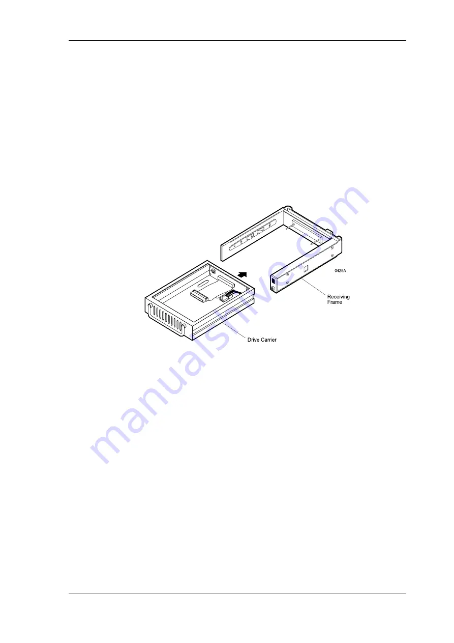
3.5” SCSI drive within a 5.25" half-height peripheral slot (Figure 2).

The DE100 allows a drive to be removed and transported to another DE100-equipped computer

or expansion chassis, and also provides the ability to secure sensitive data by removing and

storing the drive safely for future use.  Up to fifteen (15) DE100 units can be attached to one

host  adapter.

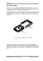
Figure 2:  DE100 Receiving Frame and Carrier

This User's Guide describes the steps required to install the StorCase Data Express

(DE100i-SW and DE100i-SWC) removable enclosure inside a computer peripheral bay or

external expansion chassis.  This guide supplements documentation provided with the host

computer system, operating system, and the drive to be installed within the Data Express

carrier.

All manuals and user guides at all-guides.com

Summary of Contents for Data Express DE100i-SW

Page 1: ...StorCase Technology Data Express DE100i SW DE100i SWC Removable SCSI Wide Single Ended Drive Enclosures User sGuide All manuals and user guides at all guides com a l l g u i d e s c o m...

Page 2: ...17600 Newhope Street Fountain Valley CA 92708 9885 Phone 714 438 1850 Fax 714 438 1847 StorCase Technology DataExpress DE100i SW DE100i SWC Removable SCSI Wide Single Ended Drive Enclosures User s Gui...

Page 3: ...of seven 7 years excepting the RAID controller power supply fan and blower components which are covered by the three year warranty described below Three Year Warranty The following StorCase products...

Page 4: ...foregoing is the complete warranty for the products identified above and supersedes all other warranties and representations whether oral or written StorCase expressly disclaims all warranties for the...

Page 5: ...Fast Transient EN 60950 CAN CSA C22 2 No 950 93 UL 1950 EN 60950 1988 EN 60950 A2 1991 EN 60950 A1 1990 FCC Part 15 Class B AS NZS 3548 Information Technology Equipment 1997 Company Name Corporate Off...

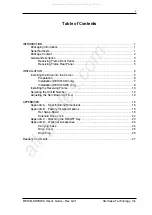
Page 6: ...tallation DE100i SW only 7 Installation DE100i SWC only 8 Installing the Receiving Frame 10 Selecting the Unit ID Number 12 Adjusting the Spin Down Up Timer 14 APPENDICES 15 Appendix A Specifications...

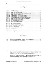
Page 7: ...17 Figure B 1 Attaching the Hot Swap Board 19 Figure B 2 Hot Swap Board Jumper Options 21 Figure B 3 Solenoid Mechanism 22 Figure C 1 Attaching the ON OFF Key 23 Figure D 1 Carrying Case 24 Figure D...

Page 8: ...seller or StorCase at 800 435 0642 to arrange for a Return Material Authorization RMA StorCase cannot ac cept returns which do not display an RMA number on the outside of the package Return the unit w...

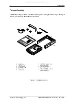
Page 9: ...6 32 Phillips Flat Hd Mounting Screws 9 1 25mm 2mmIDSelectCable DE100i SW only 1 CableCover 2 AlignmentTool 3 DriveLockKeys 4 ReceivingFrame 5 Drive Carrier 6 InsertSheet 1 2 3 4 7 8 5 6 9 Data Expre...

Page 10: ...pansion chassis and also provides the ability to secure sensitive data by removing and storing the drive safely for future use Up to fifteen 15 DE100 units can be attached to one host adapter Figure 2...

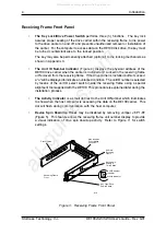
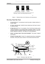
Page 11: ...playedtoindicateanunlockedcondition TheunitIDnumberisselected by means of the unit ID select switch inside the receiving frame using a special alignment tool supplied with the DE100 This procedure is...

Page 12: ...d Pins 15 20 of this connector provide unit SCSI ID selection for the computer system or expansion chassis For remote ID selection through an expansion chassis the unit ID must be set to 0 or open no...

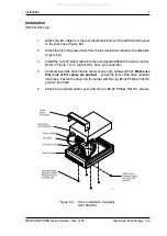
Page 13: ...itions on the disk drive and remove any jumper plugs in this area The SCSI ID cable will be installed into this section of the drive 5 SCSI ID Cable DE100i SW only Figure 7 The DE100i SW carrier is su...

Page 14: ...sk drive Figure 6A 3 Install the 5 pin ID select cable into the rear signal distribution board connector Refer to Figure 7 for a typical 2mm drive pin connection 4 Carefully insert the drive into the...

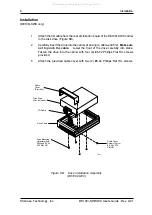
Page 15: ...ble from the rear distribution board of the DE100i SWC carrier to the disk drive Figure 6B 2 Carefully insert the drive into the carrier at an angle cable end first Make sure not to pinch the cable Lo...

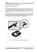
Page 16: ...he ID select cable to the drive using the 2mm connectors Align the ID0 pin with the black wire Attach the 1 25mm connector on the other end of the ID select cable to the 1 25mm connector J3B provided...

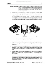
Page 17: ...any expansion boards that may make installation difficult 3 To select the DE100 unit ID remotely through the computer system or external expansion chassis the appropriate cable from the system must b...

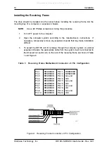
Page 18: ...a daisy chain the terminators on the receiving frame must be enabled If the DE100 is in the middle of a daisy chain termination should be disabled Refer to jumper W2 in Figure 5 IMPORTANT NOTE In orde...

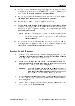
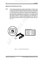
Page 19: ...initialized prior to use with the operating system and applications software Refer to the drive and or computer manufacturer s documentation for formatting information Selecting the Unit ID Number 1 V...

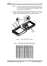
Page 20: ...Unit ID Display Figure 10 Unit ID Select Switch Location NOTE The lock on the DE100 receiving frame serves two functions 1 as a lock to secure the drive and 2 as a DC power switch for the carrier uni...

Page 21: ...y is turned to the OFF position and when the timer receives a No SCSI Activity signal from the Hot Swap Board it waits the specified delay time before displaying a u on the front panel of the receivin...

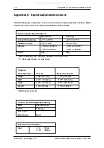
Page 22: ...DE100i SW SWC User s Guide Rev G01 StorCase Technology Inc Appendix A Specifications Dimensions 15 APPENDICES All manuals and user guides at all guides com...

Page 23: ...90 Altitude 1000 to 50 000 ft 1000 to 50 000 ft 304m to 15240m 304m to 15240m Shock 2 10g 60g 1 Non condensing with maximum gradient of 10 per hour 2 11 msec pulse width 1 2 sine wave Physical Specif...

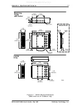
Page 24: ...2 x 8 Receiving Frame with Carrier Carrier Only 8 18 207 8mm 0 25 6 4mm 0 15 3 8mm 3 13 79 5mm 5 50 139 7mm 6 32 x 4 Bottom 1 68 42 7mm 4 67 118 6mm 7 38 187 5mm 0 25 6 4mm 0285A 1 75 44 5mm 3 75 95 3...

Page 25: ...reboot activity will force the SCSI host adapter to rescan its SCSI bus for physically attached drives and will then be able to access the new or changed drive Attaching the Hot Swap Board The DE100i...

Page 26: ...Options 19 Figure B 1 Attaching the Hot Swap Board 4 Attach the Hot Swap Board to the receiving frame motherboard by using the two screws removed earlier and insert them through the Hot Swap Board in...

Page 27: ...rtain other users are not accessing the target drive then disable it from the network Dismount the drive 2 Turn the DE100 key lock mechanism located on the front of the receiving frame clockwise to th...

Page 28: ...ns The jumpers on the Hot Swap Board are similar to those on the standard SCSI Data Express Motherboard See Figure B 2 for the Hot Swap Board jumper options Make sure the factory installed jumper is a...

Page 29: ...Seagate Barracuda drives require up to 50 seconds Refer to the drive manufacturer s documentation for specific drive information The solenoid lock is controlled by a timing switch located on the side...

Page 30: ...s OFF to the receiving frame Locate the rectangular shaped key lock mecha nism access hole on the inside of the receiving frame Note that the pawl is in an upright position Insert the key into the key...

Page 31: ...tic carrying case is designed to transport the DE100 carrier from one site to another in a safe impact and moisture resistant environment Its compact dimensions 7 long x 9 wide x 3 5 high make it easy...

Page 32: ...The full drive cover P N DX100 COV is an attractive metal cover which can provide additional protection to the drive preventing foreign material from coming in contact with the drive and cables The fu...

Page 33: ...100 PLUG is designed to fill system or external enclosure bays that are occupied by receiving frames that have no carrier units installed The purpose of the plug is to provide an attractive and functi...

Page 34: ...ons Everyone at StorCase Technology is working toward the goal of providing you with the highest quality most cost effective products available on the market and we need your comments to guide our eff...

Page 35: ...UT ALONG THIS LINE FROM BOTTOM TO TOP OF PAGE BUSINESS REPLY MAIL POSTAGE WILL BE PAID BY ADDRESSEE NO POSTAGE NECESSARY IF MAILED IN THE UNITED STATES FIRST CLASS MAIL PERMIT NO 10686 SANTA ANA CA TE...

Reviews: