
DE100i-SW/SWC User's Guide - Rev. G01
StorCase Technology, Inc.
Installation
11
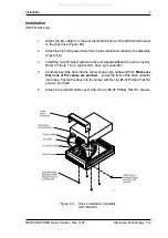
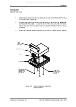
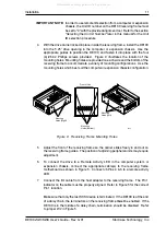
Mounting
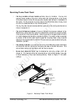
Holes (Right)
Mounting
Holes (Bottom)
Front of Unit
Mounting
Holes (Left)
0086
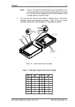
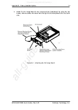
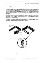
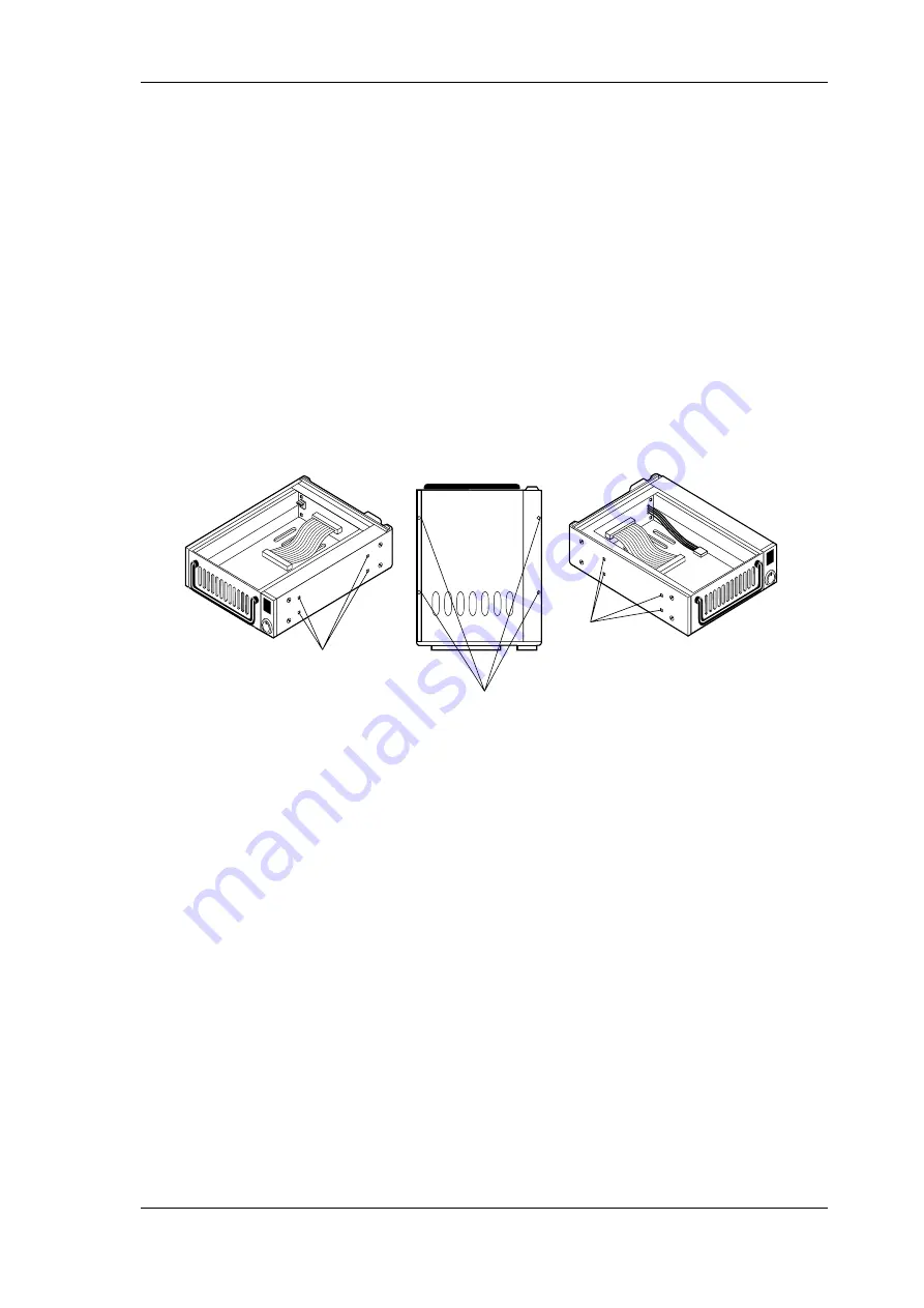
Figure 9: Receiving Frame Mounting Holes
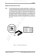
5.
Adjust the front of the receiving frame so the carrier slides freely in and out on
the receiving frame guides. The position of adjoining peripheral units may require
adjustment.
6.
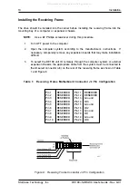
To connect the drive to a Remote Activity LED in the computer system or
expansion chassis, connect the appropriate cable(s) to the receiving frame
motherboard as shown in Figure 5. Connect J6 Pins 4 & 6 to a remote activity
LED.
7.
Connect the I/O cable from the host adapter to the receiving frame. The Pin 1
indicator on the cable must be properly aligned. Refer to Figure 5 for the correct
Pin 1 location.
Make sure that only the last SCSI device is terminated. If the DE100 is at the end
of a daisy chain, the terminators on the receiving frame
must
be enabled. If the
DE100 is in the middle of a daisy chain, termination should be disabled. Refer
to jumper W2 in Figure 5.
IMPORTANT NOTE:
In order to use remote ID selection from a computer or expansion
chassis, the Unit ID number on the DE100 receiving frame must
be set to "0" with the provided alignment tool. Refer to the section
"
Selecting the Unit ID Number
" later in this manual for the Unit
ID selection procedure.
4.
With the drive carrier locked in place inside the receiving frame, install the DE100
into the 5.25 drive opening in the computer or expansion chassis. Use the
appropriate guides to position the DE100, and fasten it into place with the four
(4) #6-32 Phillips screws provided. Figure 9 illustrates the location of the
mounting holes. Mounting holes are provided on each side and the bottom of the
receiving frame to accommodate a variety of mounting configurations. Use the
mounting holes which best suit the computer or expansion chassis configuration.
All manuals and user guides at all-guides.com


