SATA-to-USB 2.0 DE110 User's Guide - Rev. A00
StorCase Technology, Inc.
Installation
9
Installing the Drive into the Carrier
1.
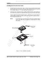
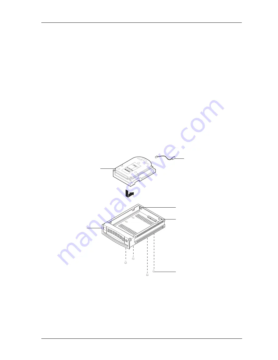
Carefully insert the drive into the carrier. Slide the drive towards the Drive Carrier
Board, so that the I/O connector on the drive mates with the connector on the Drive
Carrier Board (Figure 6). Turn the drive/carrier assembly over.
2.
Fasten the drive into place with four (4) #6-32 Phillips Flat Hd. screws (Figure 6).
Some drives may require minor adjustment before securing into carrier with screws.
If drive supports the Activity Indicator feature, connect one end of the Activity In-
dicator Cable (provided) to the drive and the other end to JP1 located on Drive
Carrier Board (Figures 4 & 6).
NOTE:
Some SATA drives provide support for the Activity Indicator feature
(refer to the SATA drive manufacturer's documentation for further
information).
Figure 6: Drive Installation Assembly
Serial ATA Drive
(Not Included)
Drive Carrier
Board
#6-32 Phillips
Flat Hd. Screw
(4 each)
Drive
Carrier
0835B
Optional Activity
Indicator Cable
(Included)
JP1
All manuals and user guides at all-guides.com
all-guides.com

