

SATA-to-USB 2.0 DE110 User's Guide - Rev. A00
StorCase Technology, Inc.
Installation
15
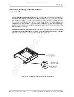
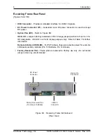
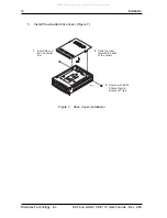
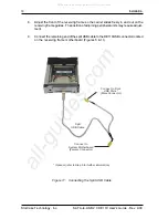
10.
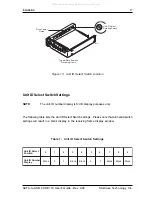
Connect the power cable from the DC power supply in the computer or expansion
chassis to the power connector on the DE110 receiving frame. Refer to Figure 5A
for the DE110 receiving frame power connector location.
11.
Replace any expansion boards that may have been removed earlier. Replace the
system cover according to the manufacturers instructions.
12.
Reconnect any system or peripheral cables removed earlier.
13.
Turn ON power to the computer. If the installation has been successful, and all
the cables have been properly attached, the system should boot normally.
Although the computer may not recognize the DE110 yet, the front panel display
on the DE110 receiving frame should illuminate.
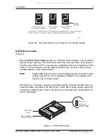
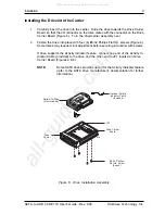
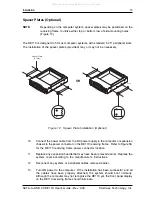
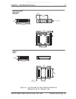
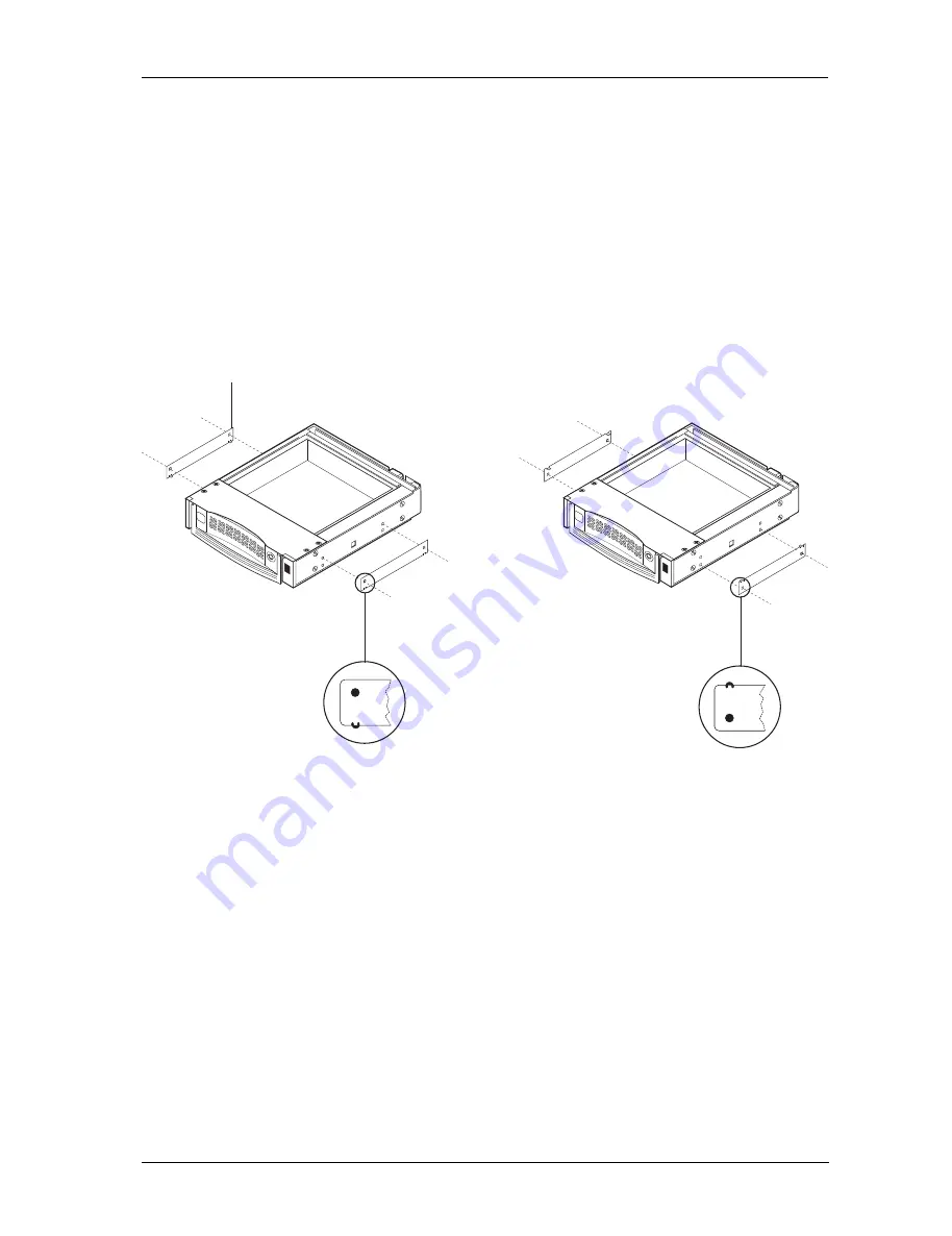
Spacer Plates (Optional)
NOTE:
Depending on the computer system, spacer plates may be positioned on the
receiving frame to utilize either top or bottom row of side-mounting holes
(Figure 12).
The DE110 is designed to fit most computer systems with standard 5.25" peripheral slots.
The installation of the spacer plates (provided) may or may not be necessary.
Figure 12: Spacer Plate Installation (Optional)
Spacer Plate
(2 Total)
OR
0869
All manuals and user guides at all-guides.com


