background image

StorCase Technology, Inc.

Ultra320 DE200 User's Guide - Rev. A01

20

Appendix D - Optional Accessories

Appendix D - Optional Accessories

Carrying Case

Drive
Carrier

DX100-DE-C
Carrying
Case

0014

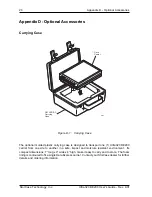
Figure D-1:  Carrying Case

The optional molded plastic carrying case is designed to transport one (1) Ultra320 DE200
carrier from one site to another in a safe, impact and moisture resistant environment.  Its
compact dimensions, 7” long x 9” wide x 4” high, make it easy to carry and to store.  The foam
lining is contoured to fit a single Data Express carrier.  Contact your StorCase dealer for further
details and ordering information.

Summary of Contents for Data Express Ultra320 DE200

Page 1: ...StorCase Technology Data Express Ultra320 DE200 Removable SCSI Wide Ultra320 Drive Enclosure User s Guide...

Page 2: ...c i StorCase Technology DataExpress Ultra320 DE200 Removable SCSI Wide Ultra320 Drive Enclosure User s Guide Part No P89 0000 0311 A01 August 2006 StorCase Technology Inc 17600 Newhope Street Fountain...

Page 3: ...tegrated into or purchased separately for use with these products which are identified and covered by the three year or hard drive warranties described below All StorCase interface cables and other ac...

Page 4: ...prior to servicing your system This warranty covers only repair or replacement of defective StorCase products as described above StorCase is not liable for and does not cover under warranty any costs...

Page 5: ...Flicker EN 55024 1998 ITE Immunity EN 61000 4 2 EN 61000 4 6 EN 61000 4 3 EN 61000 4 8 EN 61000 4 4 EN 61000 4 11 EN 61000 4 5 CAN CSA C22 2 No 950 95 UL 1950 EN 60950 2000 FCC Part 15 Class A AS NZS...

Page 6: ...nel 5 INSTALLATION 7 Preparation 7 Installation 7 Installing the Receiving Frame 9 Selecting the Unit ID Number 12 Adjusting the Spin Down Up Timer 14 APPENDICES 15 Appendix A Specifications Dimension...

Page 7: ...320 DE200 Physical Dimensions 17 Figure B 1 Solenoid Mechanism 18 Figure C 1 Attaching the ON OFF Key 19 Figure D 1 Carrying Case 20 Figure D 2 Full Drive Cover 21 Figure D 3 Drive Plug 22 List of Tab...

Page 8: ...d please call your reseller or StorCase at 800 435 0642 to arrange for a Return Material Authorization RMA StorCase cannot accept returns which do not display an RMA number on the outside of the packa...

Page 9: ...acement Figure 1 Package Contents 1 2 3 4 7 5 6 Data Express Dri ve Ca rrie r Dis k Dri ve No t Inc lud ed Po we r Ca ble I O Ca ble Dri ve Mo unt ing Ha rdw are 4e a Ph illip s 6 3 2 x 3 1 6 Fla t HD...

Page 10: ...cated by the Ultra320 logo The StorCase Technology Data Express Ultra320 DE200 is composed of a receiving frame which supports SCSI Ultra320 interfaces and fits within a 5 25 half height peripheral sl...

Page 11: ...rier is Installed and Locked in the receiving frame or if the carrier is Removed from the receiving frame If the carrier is Installed but Not Locked in the receiving frame a u will be displayed to ind...

Page 12: ...of this connector are provided for remote unit SCSI ID selection through the computer system Remote ID selection requires that the unit ID switch located on the inside of the receiving frame be set to...

Page 13: ...m the SCSI bus NOTE Do not remove this jumper Factory Installed Jumpers J3 There are two 2 jumpers factory installed on J3 One jumper is located on Pins 7 8 the other on Pins 9 10 J3 J4 P1 DC Power Co...

Page 14: ...o refer to the manufacturer s documentation provided with the drive 1 Remove the drive from its protective packaging 2 SCSI Drive Termination The DE200 does not provide onboard termination External te...

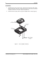
Page 15: ...rew 4 each Drive Carrier Drive Carrier Board Installation 1 Carefully insert the drive into the carrier Slide the drive towards the Drive Carrier Board so that the I O DC power and ID select connector...

Page 16: ...the Ultra320 DE200 requires Ultra320 drives Ultra320 HBA and Ultra320 compliant cabling internal and external Use a 2 Phillips screwdriver during this procedure The drive should be installed into the...

Page 17: ...appropriate guides to position the DE200 and fasten it into place with the four 4 6 32 Phillips screws provided Figure 8 illustrates the location of the mounting holes Mounting holes are provided on e...

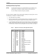
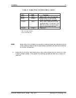
Page 18: ...so the carrier slides freely in and out on the receiving frame guides The position of adjoining peripheral units may require ad justment Table 2 Option Pins 13 16 Drive Motor Control Open Open Motor...

Page 19: ...er 11 Turn ON power to the computer If the installation has been successful and all cables have been properly attached the system should boot normally Although the computer may not recognize the DE200...

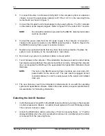
Page 20: ...nside the receiving frame 4 After selecting an appropriate unit ID number replace the DE200 carrier in the receiving frame and LOCK IT IN PLACE NOTE The lock on the DE200 receiving frame serves two fu...

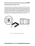
Page 21: ...rame The amount of time required for a disk drive to spin down is approximately 15 seconds or more This number can vary depending on the type of SCSI device and manufacturer e g a Seagate Barracuda ma...

Page 22: ...Ultra320 DE200 User s Guide Rev A01 StorCase Technology Inc Appendix A Specifications Dimensions 15 APPENDICES...

Page 23: ...our 2 11 msec pulse width 1 2 sine wave Physical Specifications Carrier Receiving Frame Height 1 68 42 7mm 1 70 43 2mm Width 4 67 118 6mm 5 75 146 1mm Depth 7 38 187 5mm 8 18 207 8mm Weight 1 2lb 0 55...

Page 24: ...00 User s Guide Rev A01 StorCase Technology Inc Appendix A Specifications Dimensions 17 Figure A 1 Ultra320 DE200 Physical Dimensions Dimensions are for reference only 373c Isolator Board DE200 Board...

Page 25: ...from 15 40 seconds depending on the type of drive being used e g Seagate Barracuda drives require up to 45 seconds Refer to the drive manufacturer s documentation for specific drive information The so...

Page 26: ...lar shaped key lock mecha nism access hole on the inside of the receiving frame Note that the pawl is in an upright position Insert the key into the key lock 2 Rotate the key 90 degrees counterclockwi...

Page 27: ...g Case The optional molded plastic carrying case is designed to transport one 1 Ultra320 DE200 carrier from one site to another in a safe impact and moisture resistant environment Its compact dimensio...

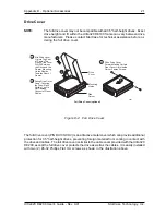
Page 28: ...e full drive cover may not be compatible with all 3 5 half height drives Exact drive height and fit within the Ultra320 DE100 frame can vary between drive manufacturers Please contact StorCase for tec...

Page 29: ...g The drive plug P N DX100 PLUG is designed to fill system or external enclosure bays that are occupied by receiving frames that have no carrier units installed The purpose of the plug is to provide a...

Page 30: ...e installation instructions Everyone at StorCase Technology is working toward the goal of providing you with the highest quality most cost effective products available on the market and we need your c...

Page 31: ...S LINE AND STAPLE SHUT CUT ALONG THIS LINE FROM BOTTOM TO TOP OF PAGE BUSINESS REPLY MAIL POSTAGE WILL BE PAID BY ADDRESSEE NO POSTAGE NECESSARY IF MAILED IN THE UNITED STATES FIRST CLASS MAIL PERMIT...

Reviews: