

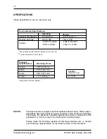
StorCase Technology, Inc.
RJR110 Users Guide - Rev. A02
3
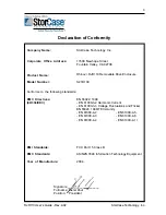
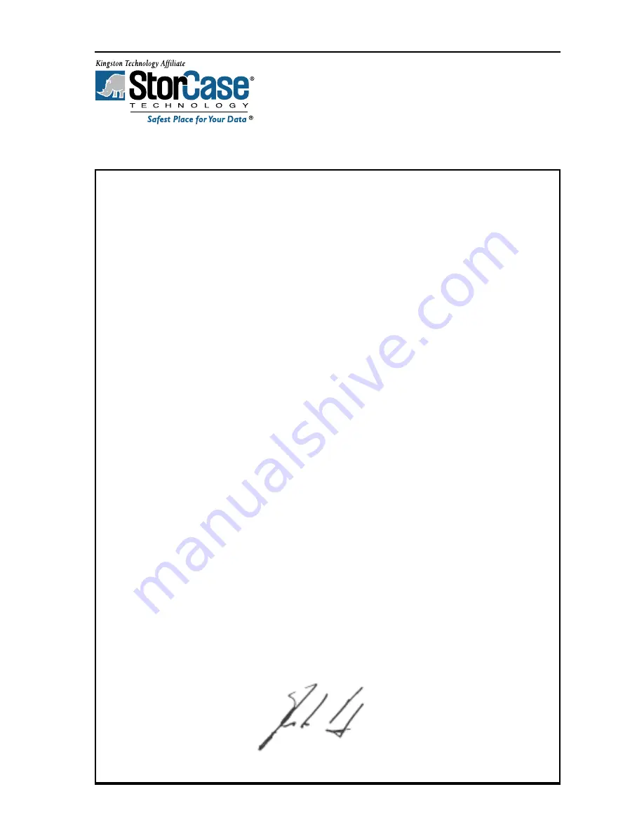
Declaration of Conformity
StorCase Technology, Inc.
17600 Newhope Street
Fountain Valley, CA 92708
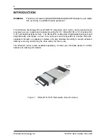
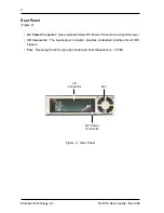
RhinoJr. RJR110 Removable Drive Enclosure
S21B109
EN 55022: 1998
- EN 61000-3-2 Harmonic Current
- EN 61000-3-3 Voltage Fluctuations and Flicker
EN 55024: 1998 ITE Immunity
- EN 61000-4-2
- EN 61000-4-5
- EN 61000-4-3
- EN 61000-4-6
- EN 61000-4-4
- EN 61000-4-11
FCC Part 15, Class B
AS/NZS 3548 Information Technology Equipment
2004
Company Name:
Corporate Office Address:
Product Name:
Model Number:
Conforms to the following standards:
EMC Directives:
(89/336/EEC)
EMI Standards:
EMC Standards:
Year of Manufacture:
Signature:___________________
Full name: Dieter Paul
Position: President


