background image

RJR110 User’s Guide - Rev. A02

StorCase Technology, Inc.

4

INTRODUCTION

WARNING:

The Rhino

JR

 contains NO USER SERVICEABLE PARTS inside the unit.  Refer

ALL servicing to qualified service personnel!

The  StorCase  Technology  Rhino

JR

  RJR110  removable  drive  carrier  and  receiving  frame

provides low cost, durable and reliable mounting for 3.5” Ultra ATA100 or 133 drives within

5.25” half-height peripheral slots.  The Rhino

JR

 is constructed of lightweight aluminum and

polycarbonate  and  allows  a  drive  to  be  removed  and  transported  to  another  Rhino

JR

-

equipped computer or expansion chassis, and also provides the ability to secure sensitive

data by removing and storing the drive safely for future use.

The Rhino

JR

 carrier is also available separately.  Contact your StorCase dealer for further

details and ordering information.

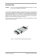
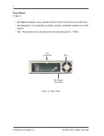
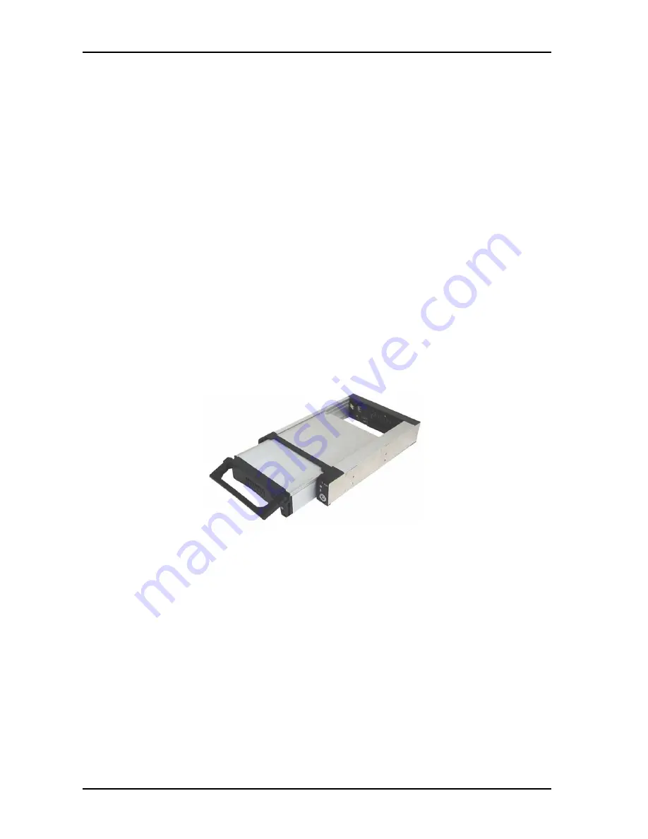
Figure  1:    RhinoJR  RJR110  Removable  Drive  Enclosure

Carrier

Receiving

Frame

Summary of Contents for Rhino JR RJR110

Page 1: ...echnology Rhino JR RJR110 IDE Removable Drive Enclosure User s Guide Part No D89 0000 0258 A02 July 2005 StorCaseTechnology Inc 17600NewhopeStreet FountainValley CA92708 9885 Phone 714 438 1850 Fax 71...

Page 2: ...cribed below All StorCase interface cables and other accessories specifically intended for use with the StorCase products identified above are also covered by this 7 year warranty Three Year Warranty...

Page 3: ...r to servicing your system This warranty covers only repair or replacement of defective StorCase products as described above StorCase is not liable for and does not cover under warranty any costs asso...

Page 4: ...Voltage Fluctuations and Flicker EN 55024 1998 ITE Immunity EN 61000 4 2 EN 61000 4 5 EN 61000 4 3 EN 61000 4 6 EN 61000 4 4 EN 61000 4 11 FCC Part 15 Class B AS NZS 3548 Information Technology Equip...

Page 5: ...or 133 drives within 5 25 half height peripheral slots The RhinoJR is constructed of lightweight aluminum and polycarbonate and allows a drive to be removed and transported to another RhinoJR equippe...

Page 6: ...carrier ON and OFF and prevents unauthorized removal or installation of the carrier For the computer to access data on the disk drive the key must be turned counterclockwise to the locked position LE...

Page 7: ...onnector Uses a standard 4 pin DC Power Connector to accept DC power I O Connector The input output connector provides a standard interface for all IDE signals Fan Receiving frame fan provides enhance...

Page 8: ...ower connector Figure 5 so that the drive connectors can mate with the carrier connectors Once the drive and carrier are mated tighten the adjustment screw to secure power connector into place Turn th...

Page 9: ...uide Rev A02 StorCase Technology Inc 8 Figure 6 Installing a Drive into the Carrier Adjust if Necessary Loosen Screw to Adjust Figure 5 Adjusting the DC Power Connector IDE Drive Not Included Bottom M...

Page 10: ...o place with the four 4 6 32 Phillips Pan Head screws provided 4 Adjust the front of the receiving frame so that the carrier slides freely in and out of the receiving frame guides The position of adjo...

Page 11: ...1 Non condensing with maximum gradient of 10 per hour 2 11 msec pulse width 1 2 sine wave Weight 1 0 lb 0 45kg Weight with NO drives installed 4 7 CFM Cooling Total for 1 Fan 1 NOTICE This User s Guid...

Reviews: