background image

56

DESCRIZIONE DI FUNZIONE

Questa turbina del tipo HVLP (High Volume, Low Pressure - alto volume, pressione bassa) lavora con un cono di condu-

zione aria regolato ad alto volume di aria e bassa pressione di esercizio. Con il sistema HVLP il fattore di nebbia di colo-

re (Overspray) è estremamente basso. I tempi di asciugatura sono ancora più brevi perchè l'aria della turbina si riscalda.

DISIMBALLAGGIO E MONTAGGIO

1. Controllare tutte le parti per eventuali danni.

2. Collegare il tubo flessibile alla turbina ed alla pistola a contenitore pendente.

PREPARAZIONE

Preparazione del materiale di rivestimento

Utilizzare esclusivamente del materiale di rivestimento fresco in contenitori nuovi. In caso di contenitori usati e già 

aperti, occorre far passare il materiale di rivestimento attraverso un setaccio per evitare un eventuale intasamento 

dell'ugello oppure un risultato di spruzzo impreciso.

Il materiale di rivestimento deve essere diluito con del solvente e secondo le indicazioni del produttore (vedasi scheda 

tecnica).

AVVERTENZA:

Il motore, a causa del suo tipo costruttivo, generare delle scintille al collettore. Quando si spruzzano dei 

liquidi infiammabili occorre posizionare la turbina sempre ad una distanza di almeno 6 metri dall'area di 

spruzzo.

FUNZIONAMENTO

1. 

Prima di mettere in funzione il sistema occorre selezionare l'ugello adatto secondo le raccomandazioni del pro-

duttore del materiale (vedasi scheda tecnica). Se l'ugello richiesto non è disponibile si consiglia di utilizzare, a seconda 

delle dimensioni dell'oggetto da spruzzare, l'ugello più grande per grandi superfici e l'ugello più piccolo per le superfici 

piccole. Un ugello da 1,3 mm è compreso nella fornitura e dovrebbe essere adatto per la maggior parte delle applicazio-

ni.

2.  Assicurarsi che siano disponibili tutti gli indumenti protettivi e tutti i dispositivi di sicurezza. Riempire il conteni-

tore per il colore.

3.  Prima di spruzzare far funzionare la turbina per alcuni minuto in modo che quest'ultima possa riscaldarsi. (Ciò otti-

mizza l'impostazione della pistola a spruzzo).

4.  Prima di iniziare a lavorare con il sistema a spruzzo, impostare il risultato di verniciatura a spruzzo su una superfi-

cie di prova.

Impostazione della pistola a spruzzo

1. 

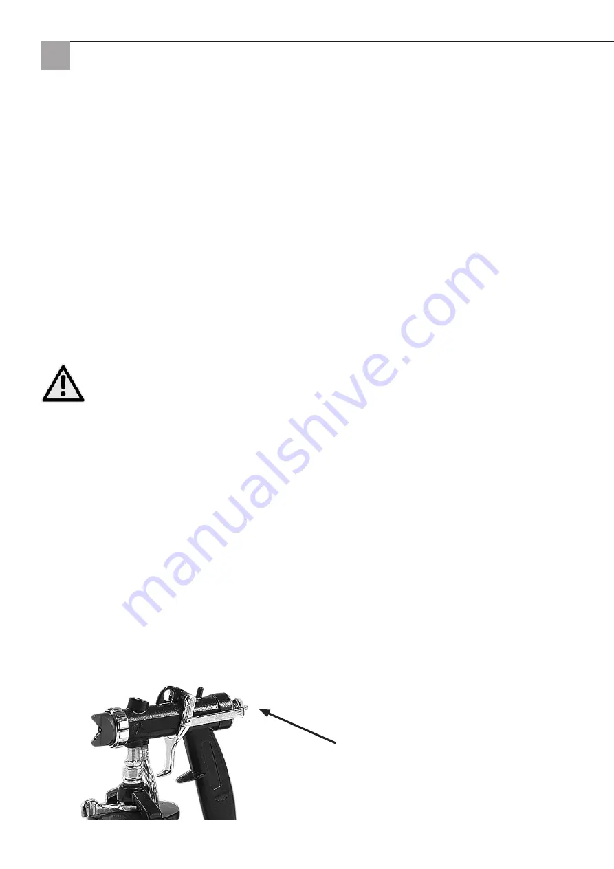
Inizialmente occorre impostare la regolazione della portata di materiale. Per avere più liquido, girare verso destra, 

per meno liquido, girare verso sinistra. Iniziare con poco materiale.

Regolazione della portata di materiale

Summary of Contents for EcoFinish HVLM

Page 1: ...VLP Spritzsystem EcoFinish HVLP spuitsysteem EcoFinish Système de projection HVLP EcoFinish Sistema a spruzzo HVLP EcoFinish EcoFinish HVLM spraying system HVLP stříkací systém EcoFinish DE NL FR IT GB CZ ...

Page 2: ...llen spritzbaren wasser und lösemittel basie renden Beschichtungsstoffen die von Materialherstellern für die Verarbeitung mit Niederdruck Spritzsystemen emp fohlen werden Dieses sind z B Lasuren Grundierungen Füller und Lacke Eine Verdünnung des Beschichtungsstoffes ist meist zwingend und nach Angaben des Materialherstellers vorzunehmen Informationen dazu erhalten Sie im tech nischen Markblatt des...

Page 3: ...ach Schlauchschnell kupplung Turbine Luftschlauch Drehzahl regulierung Ein Aus Schalter Luftkappe Düse Spannverschluss Hängebecher Materialmengen regulierung Pistolenabzug Luftschlauch für Hängebecher Schlauchanschluss Tragegriff ...

Page 4: ...b die Steckdose ordnungsgemäß geerdet ist muss dies von einer Elektrofachkraft geprüft werden Bei tech nischen Störungen am Werkzeug sorgt die Erdung durch einen geringen Widerstand für eine Ableitung der Elektrizität fern vom Anwender b Körperkontakt mit geerdeten Oberflächen wie z B Rohren Heizkörpern meiden Bei Körperkontakt zu geerdeten Oberflächen besteht erhöhte Stromschlaggefahr c Elektrowe...

Page 5: ... Personen benutzt werden e Elektrowerkzeuge müssen gepflegt werden Kontrollieren ob bewegliche Teile fehlerhaft justiert sind oder klemmen ob Teile gebrochen sind oder ob Bedingungen vorliegen welche die Funktion des Werk zeuges beeinträchtigen Bei Beschädigungen Werkzeug vor Gebrauch reparieren lassen f Das Elektrowerkzeug und Zubehör usw in Übereinstimmung mit diesen Anweisungen und in der für d...

Page 6: ... Spritzmaske Atemschutzmaske Handschuhe und Augenschutz während der Spritzarbeiten tragen GRUNDSÄTZLICH sicherstellen dass eine ordnungsgemäß gewartete Feuerlöscheinrichtung zur Verfü gung steht STETS DEN SPRITZBEREICH KONTROLLIEREN Den Arbeitsbereich von Hindernissen freihalten Für ausreichende Belüftung des Arbeitsbereichs sorgen damit sich Dämpfe und Nebel verflüchtigen kön nen NIEMALS entflamm...

Page 7: ...bel in einwandfreiem Zustand befindet Bei Verwendung eines Verlängerungskabels sicherstellen dass dieses dem Anschlusswert des Geräts entspricht Verwenden Sie Kabel mit einem Querschnitt von 2 5 mm 2 Schlauch Nur geerdete Schläuche verwenden 3 Spritzpistole Erdung wird durch Anschluss an ordnungsgemäß geerdeten Schlauch und Turbine erreicht SPRITZEN VON UND REINIGEN MIT ENTFLAMMBAREN FARBEN UND LÖ...

Page 8: ...m Kollektor Funken Beim Spritzen entflammbarer Medien die Turbine grundsätzlich mindestens 6 Meter vom Spritzbereich entfernt aufstellen BETRIEB 1 Bevor das System in Betrieb genommen wird ist die richtige Düsenauswahl nach Empfehlung des Materialher stellers zu treffen siehe Technisches Merkblatt Ist nicht genau die Düsebgröße verfügbar die dort angegeben ist ver wenden Sie je nach Objektgröße di...

Page 9: ...Düsensatz Auswahl Der Düsensatz besteht aus einer Düse und einer Luftkappe Diese Teile bilden einen passenden Satz Die Düsennadel ist für alle Düsensätze gleich und verbleibt bei einem Düsenwechsel in der Pistole Folgende Düsen und Luftkappen befinden Sich im Lieferumfang 1 Düse 1 3 mm mit roter Luftkappe 2 Düse 1 7 mm mit roter oder blauer Luftkappe je nach Beschichtungsstoff und Spritzergebnis 3...

Page 10: ...her geben Pistole in Betrieb nehmen und so lange spülen und wiederholen bis nur noch sauberes Lösemittel aus der Pistole austritt ACHTUNG Bei Lösemittel basierenden Lösemittel für optimale Belüftung sorgen den Flammpunkt des Lösemittels beachten persönliche Schutzausrüstung tragen Turbine mindestens 6 m von der Pistole entfernt aufstellen 4 Die Luftkappe und Düse entfernen und mit einer weichen Re...

Page 11: ...11 Schaltplan Erdung Schalter weiss weiss Überlasteinheit und Drehzahlregelung schwarz schwarz Kohlebürste Kohlebürste ...

Page 12: ...12 Detailzeichnung Turbine ...

Page 13: ... 05 33 Schalldämmung unten 1 36 68 05 34 Bodenplatte 1 37 68 05 36 Netzkabel 1 Pos Art Nr Bezeichnung St 38 68 05 37 Schraube M4 x 16 2 39 68 05 38 Kabelschelle 1 40 68 05 39 Zahnscheibe M4 1 41 68 05 41 Mutter M4 2 42 68 05 42 Kabelbewehrung 1 43 68 05 43 Drehzahlregler 1 44 68 05 44 Ein Aus Schalter 1 45 68 05 46 Schalterschutzkappe 1 48 68 05 47 Drehzahlreglerknopf 1 49 68 05 48 Schalldämmung l...

Page 14: ...14 Detailzeichnung HVLP Pistole ...

Page 15: ...adel Set komplett 1 5 68 05 09 Luftkappe rot mit Haltering für EcoFinish Pistole 1 6 68 05 11 Luftkappe blau mit Haltering für EcoFinish Pistole 1 7 68 00 02 Düse 1 3 mm für EcoFinish Pistole 1 8 68 00 03 Düse 1 7 mm für EcoFinish Pistole 1 9 68 00 04 Düse 2 5 mm für EcoFinish Pistole 1 10 68 00 06 Düse 3 0 mm für EcoFinish Pistole 1 11 68 01 03 Becherdichtung 1 12 68 0512 Set Anschlussnippel Luft...

Page 16: ...uvor bitten wir Sie uns unter unserer kostenlosen STORCH Service Hotline 08 00 7 86 72 47 zu kontaktieren Gewährleistungs bzw Garantieanspruch Reparaturansprüche bestehen ausschließlich an Werkstoff oder Fertigungsfehler sowie ausschließlich bei bestim mungsgemäßer Verwendung des Geräts Verschleißteile wie z B Luftfilter Düsen und Nadeln Dichtungen an der Pistole und Kohlebürsten fallen nicht unte...

Page 17: ...stimmten Änderung des Gerätes verliert diese Erklärung ihre Gültigkeit Bezeichnung des Gerätes Niederdruck Spritzsystem Geräte Typ EcoFinish Angewandte Richtlinien 2006 95 EC 2006 42 EC EN 60335 1 2002 A1 2004 A11 2004 A12 2006 A2 2006 A13 2008 A14 2010 EN 62233 2008 EN 50144 2 7 2000 except of clause 13 clause 21 101 von EN 60335 2 79 2009 IEC 60335 2 79 ed2 am1 am2 Bevollmächtigter für die Zusam...

Page 18: ...ie 32 EG conformiteitverklaring 33 Levering HVLP spuitsysteem EcoFinish inclusief luchtfilter 6 m luchtslang met snelkoppeling EcoFinish pistool met 1 3 mm sproeikop en rode luchtkap sproeikop 1 7 mm en 2 5 mm blauwe luchtkap sproeikopsleutel Technische gegevens Aantal turbines 3 Luchtvermogen 2 800 l min Maximale werkdruk 0 41 bar Maximale slanglengte 6 m Stroomvoorziening 230 V 50 Hz 6 1 A Elekt...

Page 19: ...aggreep Filtervak Slangsnelkoppeling turbine Luchtslang Toerentalinstelling Aan Uit schakelaar Luchtkap Sproeierkop Spansluiting Hangbeker Instelling materiaal hoeveelheid Pistooltrekker Luchtslang voor hangbeker Slangaansluiting ...

Page 20: ...ektricien laten controleren Bij technische storingen aan het gereedschap zorgt de aarding door een lagere weerstand voor het afleiden van de elektriciteit weg van de gebruiker Raak geen geaarde oppervlakken aan zoals buizen warmtebronnen Bij lichamelijk contact met geaar b de oppervlakken bestaat kans op elektrische schokken Elektrische gereedschappen niet blootstellen aan regen of vochtigheid Wat...

Page 21: ...es Elektrisch gereedschap moet worden onderhouden Controleer of bewegende delen onjuist zijn inge e steld of klemmen of er delen defect zijn of dat er omstandigheden zijn die van nadelige invloed op de wer king van het apparaat zijn Bij beschadigingen het gereedschap voor gebruik laten repareren Gebruik het elektrisch gereedschap en de accessoires etc in overeenstemming met deze instructies f gebr...

Page 22: ...eeft gelezen ALTIJD een spuitmasker ademmasker handschoenen en oogbescherming dragen tijdens de spuitwerk zaamheden ALTIJD controleren of er een correct onderhouden blusapparaat beschikbaar is ALTIJD HET SPUITBEREIK CONTROLEREN Zorg ervoor dat er zich geen hindernissen op de werkplek bevinden Zorg voor voldoende ventilatie van de werkplek zodat dampen en nevel kunnen vervluchtigen NOOIT ontvlambaa...

Page 23: ...abel in perfecte toestand is Controleer bij gebruik van een verlengkabel dat deze met de aansluit waarde van het apparaat overeenkomt Gebruik een kabel met een diameter van 2 5 mm Slang alleen geaarde slangen gebruiken 2 Spuitpistool aarding wordt bereikt door aansluiting op een correct geaarde slang en turbine 3 SPUITEN VAN EN REINIGEN MET ONTVLAMBARE VERF EN OPLOSMIDDELEN Bij spuiten van ontvlam...

Page 24: ...ij spuiten van ontvlambare mediums de turbi ne altijd minstens 6 meter van het spuitgebied opstellen GEBRUIK 1 Voordat het systeem in gebruik wordt genomen moet de juiste sproeikop op basis van de aanbeveling van de materiaalfabrikant worden gekozen zie technisch gegevensblad Als de sproeikop die daar staat aangegeven niet pre cies beschikbaar is gebruik dan afhankelijk van de objectgrootte de vol...

Page 25: ...n sproeikopset De sproeikopset bestaat uit een sproeikop en een luchtkap Deze onderdelen vormen samen een passende set De spro eikopnaald is voor alle sets gelijk en blijft bij wisselen van de sproeikop in het pistool De volgende sproeikoppen en luchthappen worden meegeleverd 1 Sproeikop 1 3 mm met rode luchtkap 2 Sproeikop 1 7 mm met rode of blauwe luchtkap afhankelijk van coatingstof en spuitres...

Page 26: ...osmiddel in de beker neem het pistool in gebruik nu net zo lang spoelen en herhalen totdat er alleen nog schoon oplosmiddel uit het pistool komt PAS OP Zorg bij oplosmiddelgebaseerde oplosmiddelen voor optimale ventilatie neem het vlampunt van het oplos middel in acht draag persoonlijke beschermingsuitrusting en stel de turbine minimaal 6 van het pistool op 4 De luchtkap en sproeikop verwijderen e...

Page 27: ...27 Schakelschema Aarding schakelaar wit wit Overlasteenheid en toerentalregeling zwart zwart Koolborstel Koolborstel ...

Page 28: ...28 Detailtekening turbine ...

Page 29: ... 35 68 05 33 Geluiddemping onder 1 36 68 05 34 Bodemplaat 1 37 68 05 36 Stroomkabel 1 Pos Art nr Benaming Ond 38 68 05 37 Schroef M 4 x 16 2 39 68 05 38 Kabelbevestiging 1 40 68 05 39 Getande borgring M4 1 41 68 05 41 Moer M4 2 42 68 05 42 Kabelversterking 1 43 68 05 43 Toerentalregelaar 1 44 68 05 44 Aan uit schakelaar 1 45 68 05 46 Beschermkap voor schakelaar 1 48 68 05 47 Toerentalregelknop 1 4...

Page 30: ...30 Detailtekening HVLP pistool ...

Page 31: ...pleet 1 5 68 05 09 Luchtkap rood met houder voor EcoFinish pistool 1 6 68 05 11 Luchtkap blauw met houder voor EcoFinish pistool 1 7 68 00 02 Sproeikop 1 3 mm voor EcoFi nish pistool 1 8 68 00 03 Sproeikop 1 7 mm voor EcoFi nish pistool 1 9 68 00 04 Sproeikop 2 5 mm voor EcoFi nish pistool 1 10 68 00 06 Sproeikop 3 0 mm voor EcoFi nish pistool 1 11 68 01 03 Bekerdichting 1 12 68 0512 Set aansluitn...

Page 32: ...te verzenden Neem eerst contact op met de STORCH Service Hotline hiervoor worden kosten in rekening gebracht 49 0 202 49 20 110 Garantieclaims Reparatieclaims zijn uitsluitend geldig bij materiaal of fabricagefouten en uitsluitend bij reglementair gebruik van het apparaat Slijtagedelen zoals luchtfilters sproeikoppen en naalden dichtingen op het pistool en koolborstels vallen niet onder dergelijke...

Page 33: ...ring van het apparaat is deze verklaring niet langer geldig Beschrijving van het apparaat Lage druk spuitsysteem Apparaattype EcoFinish Toegepaste richtlijnen 2006 95 EC 2006 42 EG EN 60335 1 2002 A1 2004 A11 2004 A12 2006 A2 2006 A13 2008 A14 2010 EN 62233 2008 EN 50144 2 7 2000 except of clause 13 clause 21 101 van EN 60335 2 79 2009 IEC 60335 2 79 ed2 am1 am2 Verantwoordelijke voor samenstellin...

Page 34: ...de conformité CE 49 Fournitures Système de projection HVLP EcoFinish comprenant filtre à air flexible à air de 6 m avec raccord rapide pistolet EcoFi nish avec buse de 1 3 mm et capot d air rouge buse de 1 7 mm et 2 5 mm capot d air bleu clé à buse Caractéristiques techniques Nombre de turbines 3 Débit d air 2 800 l mn Pression de service maximale 0 41 bar Longueur maximale du flexible 6 m Aliment...

Page 35: ...t filtre Raccord rapide pour flexible de la turbine Flexible à air Régulation du régime Commutateur Marche Arrêt Capot d air Buse Sauterelle Godet suspendu Régulation du débit de matériau Gâchette du pistolet Flexible à air pour godet suspendu Raccord du flexible ...

Page 36: ...erre correcte de la prise un élec tricien qualifié devra effectuer un contrôle En cas de dérangements techniques survenant sur l outil la mise à la terre garantit une dérivation de l électricité loin de l utilisateur grâce à une faible résistance Eviter tout contact corporel avec des pièces mises à la terre comme par exemple des tuyauteries des b radiateurs En cas de contact corporel avec des surf...

Page 37: ...en e ajustées ou ne sont pas bloquées qu il n y a pas d endommagements ainsi que l état des pièces et l absence de conditions portant préjudice au bon fonctionnement de l outil En cas d endommagement de l outil le faire réparer avant toute utilisation Utiliser l outil électrique les accessoires etc conformément aux présentes instructions au mode f d utilisation prescrit pour cet outil électrique s...

Page 38: ...et n ait lu le présent manuel de service TOUJOURS porter un masque de projection masque de protection respiratoire des gants et des lunettes protectrices pendant les travaux de projection S assurer PAR PRINCIPE qu un extincteur d incendie entretenu comme il se doit est prévu CONTRÔLER CONSTAMMENT LA ZONE DE PROJECTION Maintenir la zone de travail exempte d obstacles Veiller à une aération suffisan...

Page 39: ...n d une rallonge il faut vérifier qu elle cor responde bien à la puissance de l appareil Utilisez un câble présentant une section de 2 5 mm Flexible n utiliser que des flexibles reliés à la terre 2 Pistolet pulvérisateur la mise à la terre est réalisée par le raccordement à une turbine et à un flexible 3 mis à la terre en bonne et due forme PROJECTION ET NETTOYAGE AVEC DES PEINTURES ET SOLVANTS IN...

Page 40: ...iveau du collecteur pour des raisons inhérentes à la construction Lors de la projection d éléments inflammables la turbine doit être généralement placée à une distance minimum de 6 mètres par rapport à la zone de projection FONCTIONNEMENT 1 Avant de mettre le système en service il convient de choisir la bonne buse conformément aux recommandations du fabricant de matériaux voir Fiche Technique Si l...

Page 41: ...eur Marche Arrêt Sélection du lot de buses Le lot de buses est composé d une buse et d un capot d air Ces pièces constituent un lot adapté L aiguille de la buse est identique pour tous les lots de buses et reste dans le pistolet en cas de changement de buses Les buses et les capots d air suivants se trouvent dans les fournitures 1 Buse de 1 3 mm avec capot d air rouge 2 Buse de 1 7 mm avec capot d...

Page 42: ...ant dans le godet mettre le pistolet en service et rincer et répéter jusqu à ce qu un solvant encore plus propre sorte du pistolet ATTENTION veiller à une aération optimale dans le cas des peintures à base de solvants respecter le point d inflammation du solvant porter des équipements de protection personnelle placer la turbine à une distance minimum de 6 m par rapport au pistolet 4 Retirer le cap...

Page 43: ...43 Schéma de connexions Mise à la terre Commutateur blanc blanc Unité de surcharge et régulateur de régime noir noir Balai de charbon Balai de charbon ...

Page 44: ...44 Schéma détaillé de la turbine ...

Page 45: ... 05 34 Plaque de sol 1 37 68 05 36 Câble d alimentation 1 Pos Référence Désignation St 38 68 05 37 Vis M 4 x 16 2 39 68 05 38 Collier de câble 1 40 68 05 39 Rondelle M4 1 41 68 05 41 Ecrou M4 2 42 68 05 42 Armure de câble 1 43 68 05 43 Régulateur de régime 1 44 68 05 44 Commutateur Marche Arrêt 1 45 68 05 46 Capuchon protecteur de commutateur 1 48 68 05 47 Bouton du régulateur de régime 1 49 68 05...

Page 46: ...46 Schéma détaillé du pistolet HVLP ...

Page 47: ...68 05 09 Capot d air rouge avec bague de retenue pour pistolet Eco Finish 1 6 68 05 11 Capot d air bleu avec bague de retenue pour pistolet Eco Finish 1 7 68 00 02 Buse de 1 3 mm pour pistolet EcoFinish 1 8 68 00 03 Buse de 1 7 mm pour pistolet EcoFinish 1 9 68 00 04 Buse de 2 5 mm pour pistolet EcoFinish 1 10 68 00 06 Buse de 3 0 mm pour pistolet EcoFinish 1 11 68 01 03 Joint du godet 1 12 68 051...

Page 48: ...cter préalablement l assistance téléphonique payante de la société STORCH 49 0 202 49 20 110 Demande de prise en garantie La garantie ne s applique qu en cas de défauts de fabrication ou de défaut des matériaux et exclusivement si l appareil a été utilisé conformément à l usage prévu Les pièces d usure telles que les filtres à air les buses les aiguilles et les joints ne peuvent faire l objet d un...

Page 49: ...s de modification de l appareil sans notre accord Désignation de l appareil système de projection à basse pression Type d appareil EcoFinish Directives appliquées 2006 95 EC 2006 42 CE EN 60335 1 2002 A1 2004 A11 2004 A12 2006 A2 2006 A13 2008 A14 2010 EN 62233 2008 EN 50144 2 7 2000 hormis la clause 13 clause 21 101 de la norme EN 60335 2 79 2009 IEC 60335 2 79 ed2 am1 am2 Responsable de la compi...

Page 50: ... aria tubo di aria da 6 m con accoppiamento rapido pistola EcoFinish con ugello da 1 3 mm e tappo aria ugelli da 1 7 mm e 2 5 mm tappo aria blu chiave per ugelli Dati tecnici Numero delle turbine 3 Portata d aria 2 800 l min Pressione massima di esercizio 0 41 bar Lunghezza massima del tubo flessibile 6 m Alimentazione elettrica 230 V 50 Hz 6 1 A Potenza 1 400 Watt Peso 8 5 kg Dimensioni lungh x l...

Page 51: ...rapi do tubo flessibile turbina Tubo di aria Regolatore numero di giri Interruttore ON OFF Tappo aria ugello Chiusura a tensione Contenitore pendente Regolazione della portata di materiale Grilletto della pistola Tubo di aria per contenitore pendente Raccordo tubo flessibile ...

Page 52: ... da un elettricista In caso di guasti tecnici all utensile la messa a terra provvede ad una bassa resistenza per scaricare l energia elettrica via dall utente Evitare il contatto del corpo con superfici messe a terra come p es tubi e radiatori Nel caso di un con b tatto del corpo con delle superfici collegate a massa sussiste un elevato pericolo di scosse elettriche Non esporre gli elettroutensili...

Page 53: ...i sono impostate in modo errato o se e sono bloccate se delle componenti sono spezzate oppure se vi sono delle condizioni che precludono un fun zionamento corretto dell utensile In caso di danneggiamenti far riparare l utensile prima del suo impiego Utilizzare l elettroutensile gli accessori ecc conformemente alle presenti istruzioni nel modo prescrit f to per questo specifico tipo di elettroutens...

Page 54: ...unzionamento SEMPRE utilizzare una maschera di protezione per verniciatura a spruzzo guanti ed occhiali protettivi durante i lavori con l apparecchio a spruzzo SEMPRE assicurarsi che sia disponibile un impianto antincendio sottoposto alla manutenzione corretta SEMPRE CONTROLLARE L AREA IN CUI VIENE UTILIZZATO L UTENSILE Rimuovere dall area di lavoro eventuali ostacoli Assicurare una sufficiente ve...

Page 55: ...onde al valore di allaccia mento dell apparecchio Utilizzare cavi una sezione dei conduttori di 2 5 mm Tubo flessibile Utilizzare esclusivamente dei tubi flessibili con messa a terra 2 Pistola a spruzzo La messa a terra è ottenuta attraverso il collegamento a un tubo flessibile e una tur 3 bina che dispongono di una messa a terra corretta SPRUZZARE E PULIRE CON VERNICI E SOLVENTI INFIAMMABILI Nel ...

Page 56: ...pruzzano dei liquidi infiammabili occorre posizionare la turbina sempre ad una distanza di almeno 6 metri dall area di spruzzo FUNZIONAMENTO 1 Prima di mettere in funzione il sistema occorre selezionare l ugello adatto secondo le raccomandazioni del pro duttore del materiale vedasi scheda tecnica Se l ugello richiesto non è disponibile si consiglia di utilizzare a seconda delle dimensioni dell ogg...

Page 57: ...i Interruttore ON OFF Selezione del kit di ugelli Il kit di ugelli comprende un ugello ed un tappo aria Questi due elementi formano un kit adatto L ago è sempre lo stesso per tutti i kit di ugelli e rimane nella pistola se si vuole cambiare l ugello I seguenti ugelli e tappi aria sono com presi nella consegna 1 Ugello 1 3 mm con tappo aria rosso 2 Ugello 1 7 mm con tappo aria rosso o blu a seconda...

Page 58: ...ttere in funzione la pistola spruzzare risciacquare e ripetere fino a che fuoriesca solo del solvente pulito dalla pistola ATTENZIONE In caso di solventi basanti su solventi occorre assicurare una ventilazione ottimale osservare il punto di infiammabilità del solvente utilizzare l equipaggiamento di protezione personale e posizionare la turbina ad una distan za di almeno 6 m dalla pistola 4 Rimuov...

Page 59: ...59 Schema elettrico Messa a terra Interruttore bianco bianco Unità di sovraccarico e regolazione del numero di giri nero nero Spazzola di carbone Spazzola di carbone ...

Page 60: ...60 Disegno dettagliato turbina ...

Page 61: ... di base 1 37 68 05 36 Cavo di alimentazione 1 Pos N art Descrizione Pz 38 68 05 37 Vite M 4 x 16 2 39 68 05 38 Serracavo 1 40 68 05 39 Disco dentato M4 1 41 68 05 41 Dado M4 2 42 68 05 42 Armatura cavi 1 43 68 05 43 Regolatore del numero di giri 1 44 68 05 44 Interruttore ON OFF 1 45 68 05 46 Calotta di protezione interruttore 1 48 68 05 47 Pulsante di regolazione del numero di giri 1 49 68 05 48...

Page 62: ...62 Disegno dettagliato pistola HVLP ...

Page 63: ...68 05 09 Tappo aria rosso con anello di bloccaggio per pistola EcoFi nish 1 6 68 05 11 Tappo aria blu con anello di bloccaggio per pistola EcoFi nish 1 7 68 00 02 Ugello 1 3 mm per pistola EcoFinish 1 8 68 00 03 Ugello 1 7 mm per pistola EcoFinish 1 9 68 00 04 Ugello 2 5 mm per pistola EcoFinish 1 10 68 00 06 Ugello 3 0 mm per pistola EcoFinish 1 11 68 01 03 Guarnizione del contenitore 1 12 68 051...

Page 64: ...da noi autorizzata Si prega di consultare prima la Hotline di servizio STORCH a pagamento 02 66 22 77 15 Diritto alla garanzia Il diritti si possono far valere solo per errori di materiale o di produzione nonché esclusivamente in caso di utilizzo appropriato dell apparecchio Componenti soggetti a logorio quali filtri dell aria ugelli e aghi guarnizioni alla pistola e spazzole di carbone non vengon...

Page 65: ...odifica apportata all utensile non concordata con noi questa dichiarazione perde ogni sua validità Denominazione dell utensile Sistema a spruzzo a bassa pressione Tipo do utensile EcoFinish Direttive applicate 2006 95 CE 2006 42 EC EN 60335 1 2002 A1 2004 A11 2004 A12 2006 A2 2006 A13 2008 A14 2010 EN 62233 2008 EN 50144 2 7 2000 except of clause 13 clause 21 101 di EN 60335 2 79 2009 IEC 60335 2 ...

Page 66: ...ion of Conformity 81 Scope of delivery EcoFinish HVLP spraying system including air filter 6 m air hose with quick coupling EcoFinish gun with 1 3 mm noz zle and red air cap nozzle 1 7 mm and 2 5 mm blue air cap nozzle spanner Technical spezification Number of turbines 3 Air flow capacity 2 800 l min Maximum working pressure 0 41 bar Maximum hose length 6 m Power supply 230V 50Hz 6 1 A Power outpu...

Page 67: ...Carry Handle Filter compartment Schlauchschnell kupplung Turbine Air hose Speed control On off switch Air cup Nozzle Toggle type fastener Suspended tank Fluid adjustment Gun trigger Air hose for suspended tank Hose connector ...

Page 68: ...n case of technical malfunctions with the tool earthing ensures a lower resistance to dissipate the electric current well away from the user Avoid body contact with earthed surfaces such as pipes radiators ranges and refrigerators There is an b increased risk of electric shock if you touch an earthed surface Do not expose power tools to rain or wet conditions Water entering a power tool will incre...

Page 69: ...untrained users Maintain power tools Check for misalignment or binding of moving parts breakage of parts and any e other condition that may affect the power tool s operation If damaged have the power tool repaired before use Use the tool and accessories etc in accordance with these instructions and in the manner intended f for the particular type of power tool taking into account the working condi...

Page 70: ...WAYS wear a spray mask respirator gloves and protective eye wear while spraying ALWAYS ensure fire extinguishing equipment is readily available and properly maintained ALWAYS INSPECT SPRAYING AREA Keep the work area free of obstacles Make sure the spraying area has good ventilation to safely remove vapors and mists NEVER keep flammable material in spraying area NEVER spray in vicinity of open flam...

Page 71: ...le is undamaged If you are using an extension cable make sure it is suitable for the power tool s rating Use cables with a wire cross section of 2 5 mm Hose use only grounded hoses 2 Spray gun grounding is obtained through connection to a properly grounded hose and turbine 3 WHEN SPRAYING CLEANING WITH FLAMMABLE PAINTS AND THINNERS When spraying flammable liquids the spraying system must be set up...

Page 72: ...rates sparks at its collector When spraying flammable materials the turbine must be set up at least 6 metres from the area to be sprayed OPERATION 1 Before using the system select the correct nozzle in line with the manufacturer s recommendations see Technical Data Sheet If you do not have the right nozzle size as stated in the data sheet use the a nozzle one size larger for lar ge surfaces or one...

Page 73: ...knob ON OFF switch Selecting a nozzle set The nozzle set comprises a nozzle and an air cap These parts form a matching set The nozzle needle is the same for all nozzle sets and stays in the gun when the nozzle is changed The following nozzles and air caps are included in the scope of supply 1 nozzle 1 3 mm with red air cap 2 Nozzle 1 7 mm with red or blue air cap depending on the coating material ...

Page 74: ...p a small quantity of solvent into the container switch on the spray gun and repeatedly flush until only clean sol vent exits the spray gun CAUTION In case of solvent based solvents ensure good ventilation observe the ignition point of the solvent use personal protective equipment set up the turbine at least 6 m from the spray gun 4 Remove the air cap and nozzle and clean with a soft cleaning brus...

Page 75: ...75 Circuit diagram Earthing Switch white white Overload unit and speed control black black Carbon brush Carbon brush ...

Page 76: ...76 Detailed drawing turbine ...

Page 77: ...sulation bottom 1 36 68 05 34 Base plate 1 37 68 05 36 Power cable 1 Pos Art No Designation qty 38 68 05 37 M4x16 Screw 2 39 68 05 38 Cable clip 1 40 68 05 39 Tooth lock washer M4 1 41 68 05 41 Nut M4 2 42 68 05 42 Cord armour 1 43 68 05 43 Speed control knob 1 44 68 05 44 ON OFF switch 1 45 68 05 46 Protective cap for switch 1 48 68 05 47 Speed control button 1 49 68 05 48 Noise insulation left s...

Page 78: ...78 Detailed drawing HVLP gun ...

Page 79: ...rd set 1 4 68 05 08 Needle set complete 1 5 68 05 09 Air cap red with holder for EcoFinish gun 1 6 68 05 11 Air cap blue with holder for EcoFinish gun 1 7 68 00 02 Nozzle 1 3 mm for EcoFinish gun 1 8 68 00 03 Nozzle 1 7 mm for EcoFinish gun 1 9 68 00 04 Nozzle 2 5 mm for EcoFinish gun 1 10 68 00 06 Nozzle 3 0 mm for EcoFinish gun 1 11 68 01 03 Container seal 1 12 68 0512 Set connecting nipple air ...

Page 80: ...ur authorised service centres Please contact the chargeable STORCH service hotline first 49 0 202 49 20 110 Your rights under our warranty or guarantee Claims for repairs only relate to materials or manufacturing defects and are subject to the intended use of the device Wear parts such as air filters seals and needles seals on the gun and carbon brushes are not covered by such claims All claims sh...

Page 81: ...se of unauthorised modification of the tool Device description Low pressure spraying system Device type EcoFinish Applicable directives 2006 95 EC 2006 42 EC EN 60335 1 2002 A1 2004 A11 2004 A12 2006 A2 2006 A13 2008 A14 2010 EN 62233 2008 EN 50144 2 7 2000 except clause 13 clause 21 101 of EN 60335 2 79 2009 IEC 60335 2 79 ed2 am1 am2 Authorised agent for compilation of the technical documents ST...

Page 82: ...ole 95 Záruka 96 Prohlášení o shodě ES 97 Rozsah dodávky HVLP Stříkací systém EcoFinish včetně vzduchového filtru 6 m vzduchové hadice s rychlospojovacím šroubením Eco Finish pistole s 1 3 mm tryskou a červený vzduchový kryt tryska 1 7 mm a 2 5 mm modrý vzduchový kryt klíč na trys ky Technické údaje Počet turbín 3 Množství protékajícího vzduchu 2 800 l min Maximální pracovní tlak 0 41 baru Maximál...

Page 83: ...vé rychlospo jovací šroubení tur bína Vzduchová hadice Regulace počtu otáček Spínač Zapnout Vypnout Vzduchový kryt Tryska Stahovací uzávěr Závěsná nádobka Regulace množství materiálu Spoušť pistole Vzduchová hadice pro závěsnou nádobku Hadicová přípojka ...

Page 84: ...Pokud vzniknou pochybnosti o tom zda je zásuvka řádně uzemněna musí ji překontrolovat kvalifikovaný elektrikář Při technických poruchách na nářadí zajistí uzemnění nízkým odporem odvedení elektřiny od uživatele Zabraňte tělesnému kontaktu s uzemněnými povrchy jako např trubkami radiátory Při tělesném kon b taktu s uzemněnými povrchy může dojít k zasažení elektrickým proudem Elektro nářadí nevystav...

Page 85: ... třeba náležitě pečovat Zkontrolujte zda nejsou pohyblivé díly chybně nastave e ny nebo nesvírají zda nejsou zlomené nebo zda se nevyskytují podmínky které ovlivňují funkci nářadí Při poškození nářadí je třeba ho nechat před použitím opravit Elektro nářadí a příslušenství atd používejte v souladu s těmito pokyny a způsobem předepsaným pro f toto speciální elektro nářadí a se zohledněním pracovních...

Page 86: ...a si návod k obsluze STÁLE používejte stříkací masku ochrannou dýchací masku rukavice a ochranu očí během stříkání ZÁSADNĚ zajistěte aby byl k dispozici řádně udržovaný hasící přístroj STÁLE KONTROLUJTE OBLAST STŘÍKÁNÍ Pracovní oblast udržujte volnou bez jakýchkoli překážek Dbejte na dostatečné větrání pracovní oblasti aby se mohly rozplynout výpary a mlha NIKDY nenechávejte v oblasti stříkání záp...

Page 87: ... Zajistěte aby prodlužovací kabel byl v technicky bezvadném stavu Při použití prodlužovacího kabelu zajistěte aby odpovídal jmenovitému příkonu přístroje Používejte kabel o průřezu 2 5 mm Hadice Používejte pouze uzemněné hadice 2 Stříkací pistole Uzemnění se dosáhne připojením řádně uzemněné hadice a turbíny 3 STŘÍKÁNÍ A ČIŠTĚNÍ HOŘLAVÝMI BARVAMI A ROZPOUŠTĚDLY Při stříkání hořlavých kapalin je tř...

Page 88: ...ktoru jiskry podle typu konstrukce Při stříkání hořlavých médií turbínu zásadně umístěte minimálně 6 metrů od oblasti stříkání PROVOZ 1 Před uvedením systému od provozu je třeba zvolit správné trysky podle doporučení výrobce materiálu viz tech nický list Pokud není k dispozici přesná velikost trysky která je tam uvedena použijte podle velikosti objektu nejbližší větší u velkých ploch a nejbližší m...

Page 89: ... Zapnout Vypnout Sada trysek výběr Sada trysek sestává z trysky a vzduchového krytu Tyto díly tvoří vhodnou sadu Jehla trysky je pro všechny sady trysek stejná a zůstává při výměně trysky v pistoli V rozsahu dodávky se nacházejí následující trysky a vzduchové kryty 1 Tryska 1 3 mm s červeným vzduchovým krytem 2 Tryska 1 7 mm s červeným nebo modrým vzduchovým krytem podle nátěrové látky a vzhledu s...

Page 90: ...uho ji vyplachujte a vyplachování dále opakujte až z pistole vychází pouze čisté rozpouštědlo POZOR U rozpouštědel na bázi rozpouštědel zajistěte optimální větrání respektujte bod vzplanutí rozpouštědla noste ochranné osobní vybavení turbínu umístěte ve vzdálenosti minimálně 6 m od pistole 4 Vzduchový kryt a trysku odstraňte a očistěte jedním z měkkých čistících kartáčků Přitom nepoškoďte otvory v...

Page 91: ...91 Schéma zapojení Uzemnění Spínač bílá bílá Jednotka přetížení a regulace počtu otáček černá černá Uhlíkový kartáček Uhlíkový kartáček ...

Page 92: ...92 Podrobný výkres turbína ...

Page 93: ...vá deska 1 37 68 05 36 Síťový kabel 1 Pol Č art Označení Kusy 38 68 05 37 Šroub M 4 x 16 2 39 68 05 38 Kabelová spona 1 40 68 05 39 Ozubený kotouč M4 1 41 68 05 41 Matice M4 2 42 68 05 42 Pancéřování kabelu 1 43 68 05 43 Regulace počtu otáček 1 44 68 05 44 Spínač Zapnout Vypnout 1 45 68 05 46 Ochranný kryt spínače 1 48 68 05 47 Knoflík regulace počtu otáček 1 49 68 05 48 Tlumení hluku levá strana ...

Page 94: ...94 Podrobný výkres HVLP pistole ...

Page 95: ... 68 05 09 Vzduchový kryt červený s přídržným kroužkem pro Eco Finish pistoli 1 6 68 05 11 Vzduchový kryt modrý s přídržným kroužkem pro Eco Finish pistoli 1 7 68 00 02 Tryska 1 3 mm pro EcoFinish pistoli 1 8 68 00 03 Tryska 1 7 mm pro EcoFinish pistoli 1 9 68 00 04 Tryska 2 5 mm pro EcoFinish pistoli 1 10 68 00 06 Tryska 3 0 mm pro EcoFinish pistoli 1 11 68 01 03 Korečkové těsnění 1 12 68 0512 Sad...

Page 96: ...tanice Kontaktujte prosím nejdříve placený hotline servis firmy STORCH 49 0 202 49 20 110 Nárok na záruku příp garanci Nároky na opravu vznikají výhradně v důsledku vady materiálu nebo výrobní vady a také výhradně při používání přístroje v souladu s určeným účelem Díly podléhající opotřebení jako např vzduchový filtr trysky a jehly těsnění u pistole a uhlíkové kartáčky nespadají do takovýchto náro...

Page 97: ...ené změně zařízení ztrácí toto prohlášení svou platnost Označení nářadí Nízkotlaký stříkací systém Typ nářadí EcoFinish Použité směrnice 2006 95 EC 2006 42 EC EN 60335 1 2002 A1 2004 A11 2004 A12 2006 A2 2006 A13 2008 A14 2010 EN 62233 2008 EN 50144 2 7 2000 except of clause 13 clause 21 101 z EN 60335 2 79 2009 IEC 60335 2 79 ed2 am1 am2 Zplnomocněnec k sestavení technických podkladů STORCH Maler...

Page 98: ...98 ...

Page 99: ...99 ...

Page 100: ...ermat Référence Désignation 68 05 00 EcoFinish complet 68 00 02 Buse de 1 3 mm 68 00 03 Buse de 1 7 mm 68 00 04 Buse de 2 5 mm 68 00 06 Buse de 3 0 mm 68 05 51 Filtre à air plissé 68 05 53 Cartouche de filtre à air Art Nr Bezeichnung 68 05 00 EcoFinish komplett 68 00 02 Düse 1 3 mm 68 00 03 Düse 1 7 mm 68 00 04 Düse 2 5 mm 68 00 06 Düse 3 0 mm 68 05 51 Faltenluftfilter 68 05 53 Luftfiltermatte Výr...

Reviews: