background image

34

Table of contents 

Page

Delivery specifications 

34

Specifications 

34

Preface 34

Area of application 

35

Operation 

35

Cleaning and maintenance 

35

Safety precautions  

35 - 36

Troubleshooting  

36

Personnel qualification 

36

Spare parts, consumables  

36

Configuration / initial operation 

37

Assembly left bearing rail (accessories) 

38

Cutting variants 

39

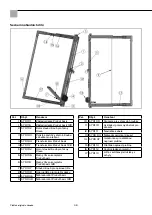
List of spare parts 

40

Warranty 41

Ec declaration of conformity 

41

Delivery specifications 

ProCut basic foam board cutter with integrated transformer,replacement wire cut to length, spare fuse, transport and 

storage case, instruction manual

Specifications


ProCut basic  

ProCut basic 128

Cutting length: 

105 cm  

128 cm

Cutting depth:  

25 cm  

25 cm

Device weight:   

9,3 kg  

10,8 kg

Cutting mode:  

Thermal  

Thermal

Fuse:  

8 A  

8 A

Cable length:  

3 metres  

3 metres

Power supply:  

230 V / 50 Hz   

230 V / 50 Hz

Preface

Reading this instruction manual is the basis for operating the ProCut basic foam board cutter. Before starting to use the 

device this instruction manual must be read carefully and in full. If there is anything you do not understand, contact us 

immediately. Do not operate the device if you are in any doubt. By starting to use the device, you confirm that you have 

read and understood the manual and assume the responsibility for its operation. The methods and procedures used for 

manufacturing and quality monitoring purposes correspond to state of the art technology. 

GB

Thank you

for purchasing a STORCH product. You have purchased a quality product.

If you would like to suggest an improvement, or experience a problem with your product, please do not hesitate to 

contact us.

Please contact your field sales representative or, in urgent cases, contact us directly.

Yours sincerely,

STORCH Service Department

Tel.:  

+49 (0)2 02 . 49 20 - 112

Fax:  

+49 (0)2 02 . 49 20 - 244

Free service hotline:  

0800 786 72 47

Toll-free order hotline: 

+49 800 7867244 

Toll-free order fax:  

+49 800 7867243


(only available in Germany)

All information is without guarantee! Subject to technical modifications and errors! 

Translation of the original instruction

Summary of Contents for ProCut

Page 1: ...ic ProCut basic 128 Dämmplattenschneider Isolatieplatensnijder Appareil de découpe pour plaques d isolation Apparecchio di taglio per pannelli isolanti Foam board cutter Řezačka izolačních desek DE NL FR IT GB CZ ...

Page 2: ...nehmen ist die vorliegende Anleitung komplett und sorgfältig durchzulesen Bestehen irgendwelche Unklarheiten sprechen Sie uns umgehend dazu an Nehmen Sie das Gerät nicht in Betrieb solange Unklarheiten bestehen Mit der Inbetriebnahme des Gerätes bestätigen Sie dass Sie die Betriebsanleitung gelesen und verstanden haben Die eingesetzten Methoden und Verfahren für die Herstellung und Qualitätsüberwa...

Page 3: ...chzuziehen Drahtführungsrollen und Auszüge sind zu reinigen und auf Leichtgängigkeit zu prüfen Bei starker Verschmutzung Verkrustung ist der Schneidedraht zu ersetzen Sicherheitshinweise ACHTUNG Alle Sicherheitshinweise lesen und beachten Schützen Sie das Gerät vor Nässe Der Betrieb im Freien bei Regen ist untersagt Für die Reinigung nur trockene Medien verwenden und keine lösungsmittelhaltigen Re...

Page 4: ...m Umfeld des Gerätes beseitigt werden z B ungesicherte Stromkabel Verpackung etc Störungen Störungsbehebung Einem störungsfreien Betrieb ist eine regelmäßige und sorgfältig Reinigung und Wartung vorausgesetzt Bei Störungs behebungen ist grundsätzlich der Trafo vom Stromnetz zu trennen Netzstecker ziehen Kontrollieren Sie die Stromzufuhr vom 230 V Netz wenn der Draht nicht heiß wird Prüfen oder wec...

Page 5: ...auf dem Gerüst angelehnt an die Hauswand eingesetzt werden Überzeugen Sie sich über die sichere Aufhän gung und korrekte Positionierung Anschließend lösen Sie die obere Nr 5 und untere Feststellschraube Nr 2 für den Schneidebügel Nr 6 öffnen diesen bis zum Anschlag und ziehen die Feststellschrauben Nr 2 und 5 wieder fest Lösen Sie die Feststellschraube Nr 7 der Auflageschiene Nr 8 und klappen dies...

Page 6: ...sic 128 befinden sich 2 Rändelschrauben s Pfeil Abb 3 zur Fixierung der linken Auflageschiene Drehen Sie diese bis zum Anschlag nach links Montage Führen Sie die linke Auflageschiene mit den geschlitzten Montageblechen über die Rändelschrauben Abb 4 und ziehen diese fest an Die linke Auflageschiene ist nun Einsatzbereit Abb 5 und 6 Abb 3 Abb 4 Abb 5 Abb 6 Originalanleitung ...

Page 7: ...f Auflageschiene Nr 8 stellen Feststellschrauben Nr 2 und 5 lösen Schneidebügel Nr 6 nach rechts schwenken bis die Gehrungshilfe Nr 11 des Schneidbügels Nr 6 mit Markierung auf der Dämmplatte übereinstimmt Feststellschrauben Nr 2 und 5 oben und unten wider festziehen Gehrungsschnitt Schrägschnitt Dachschräge einmalig mittels Messen oder Schmiege Art Nr 36 82 00 nicht im Lieferumfang auf Dämmplatte...

Page 8: ...Cut basic 6 57 01 06 Schneidebügel komplett ProCut basic 128 7 57 01 07 Feststellschraube für Auflageschiene 8 57 01 08 Auflageschiene für Dämmplatte 9 57 00 46 Ersatzdraht ProCut basic 9 57 00 48 Ersatzdraht ProCut basic 128 Ersatzteilliste Pos Art Nr Bezeichnung 10 57 01 09 Skala für Tiefenausschnitte 11 57 01 10 Gehrungshilfe ausklappbar 12 57 01 11 Kabelaufwickler 13 57 00 04 Ersatzsicherung 2...

Page 9: ...ung von Reparaturen Sämtliche Reparaturen dürfen ausschließlich durch unser Werk oder von STORCH autorisierten Service Stationen durchgeführt werden EG Konformitätserklärung Name Anschrift des Ausstellers STORCH Malerwerkzeuge Profigeräte GmbH Platz der Republik 6 D 42107 Wuppertal Hiermit erklären wir dass das nachstehend genannte Gerät aufgrund dessen Konzipierung und Bauart sowie in der von uns...

Page 10: ...moet u absoluut eerst deze bedieningshandleiding volledig en zorgvuldig lezen Ze vormt de basis voor de bediening van het apparaat Als er zaken onduidelijk zijn doet u er goed aan meteen contact met ons op te nemen Door de ingebruikstelling van het apparaat bevestigt u dat u de gebruikshandleiding hebt gelezen en begrepen De gebruikte methodes en procedés voor de productie en kwaliteitsbewaking be...

Page 11: ...den gereinigd en er moet worden gecontroleerd of ze lichtlopend zijn In geval van sterke vervuiling verkorsting dient de snijdraad te worden vervangen Veiligheidsrichtlijnen Bescherm het apparaat tegen vocht Het mag niet worden gebruikt in de regen Voor de reiniging enkel droge middelen gebruiken en geen reinigingsmiddelen op basis van tinner Bij het snijden ontstaat er rook Die bevat extreem geri...

Page 12: ...s en een oorzaak voor struikelen kan zijn bv rondslingerende elektrische kabels verpakking enz Storingen opheffen van storingen Voor een storingsvrij gebruik moet het apparaat absoluut regelmatig en zorgvuldig worden gereinigd Als storingen wor den verholpen moet de transfo principieel worden losgekoppeld van het stroomnet en de stekker uit het stopcontact Controleer de stroomtoevoer van het 230 V...

Page 13: ...vrijstaand of op de steiger leunend tegen de huismuur worden gebruikt Vergewis er u van dat de ophanging veilig is en zich in de juiste positie bevindt Aansluitend draait u de bovenste nr 5 en de onderste borgschroef nr 2 voor de snijbeugel nr 6 los opent deze tot aan de aanslag en trekt de borgschroeven nr 2 en 5 weer aan Draai de borgschroef nr 7 van de draagrail nr 8 los en klap deze naar recht...

Page 14: ...ProCut basic 128 bevinden zich 2 kartelschroeven zie pijl afb 3 om de linker opleghouder vast te zetten Draai deze tot de aanslag naar links Montage Breng de linker opleghouder met de gespleten montageplaten boven de kartelschroeven afb 4 een draai deze vast De linker opleghouder is nu klaar voor gebruik afb 5 en 6 Afb 3 Afb 4 Afb 5 Afb 6 Vertaling van de originele handleiding ...

Page 15: ... de snijbeugel nr 6 overeenstemt met de markering op de isolatie plaat Borgschroef nr 7 fixeren en snijdraad door de plaat leiden Schuine snede Schuine en versteksnede Deze snede wordt uitgevoerd zoals bij de versteksnede en de schuine snede De plaat kan bij de uitvoering van de schuine snede ook nog onder verstek worden gesneden Fels en dieptesnede Dakhelling een keer meten of met behulp van de z...

Page 16: ...nijdbeugel compleet ProCut basic 128 7 57 01 07 Vergrendelingsschroef voor opleghouder 8 57 01 08 Opleghouder voor isolatieplaat 9 57 00 46 Vervangende draad ProCut basic 9 57 00 48 Vervangende draad ProCut basic 128 Pos Art nr Benaming 10 57 01 09 Meetschaal voor diepte snijden 11 57 01 10 Verstekhulp uitklapbaar 12 57 01 11 Kabelopwikkelaar 13 57 00 04 Vervangende zekering 2 stuks 14 57 00 37 Is...

Page 17: ...rblijkelijk niet in acht nemen van de gebruiksaanwijzing Reparaties uitvoeren Reparaties mogen uitsluitend door onze fabriek of door STORCH geautoriseerde servicestations worden uitgevoerd EG conformiteitsverklaring Naam adres van de opsteller STORCH Malerwerkzeuge Profigeräte GmbH Platz der Republik 6 D 42107 Wuppertal Bij deze verklaren wij Dat het hieronder vermelde apparaat op basis van zijn o...

Page 18: ...areil en service il faudra lire le mode d emploi complètement et soigneusement En cas d ambiguïtés ou de flou dans le texte veuillez nous en aviser sans délai Ne commencez à pas à employer l appareil si quelque incertitude subsiste Par votre mise en service de l appareil vous confirmez avoir lu et compris le mode d emploi Les méthodes et processus de fabrication et de contrôle de qualité correspon...

Page 19: ...ls soient capables de se mouvoir sans problèmes En cas d encrassement prononcé incrustation il faudra remplacer le fil de coupe Consignes de sécurité Veiller à sa propre sécurité Mettre l appareil à l abri de l humidité Il est interdit de l utiliser sous la pluie à l extérieur Au nettoyage uniquement se servir de matériel sec ne pas utiliser de nettoyants à base de solvant La découpe provoque de l...

Page 20: ...sceptibles de provoquer trébuchages chutes câbles électriques non fixés emballages qui traînent etc Les pannes et comment y remédier Le bon fonctionnement de l appareil présuppose un nettoyage et une maintenance effectués soigneusement et régulière ment En cas de réparation il est essentiel de débrancher d abord le transfo du secteur Tirer la fiche hors de la prise de courant Contrôlerl alimentati...

Page 21: ...de manière autonome soit appuyé sur l échafaudage Assurez vous de la bonne suspension et de la position correcte du dispositif Sur ce desserrer les vis de serrage du haut n 5 et du bas n 2 de l étrier de coupe n 6 que vous ouvrirez jusqu à la position de butée puis resserrer les vis de serrage n 2 et 5 Desserrer la vis de serrage n 7 du rail d appui n 8 rabattre ce dernier vers la droite jusqu à l...

Page 22: ...s moletées cf flèche illustration 3 pour la fixation du rail d appui gauche Visser celles ci vers la gauche jusqu à la butée Montage Passer le rail d appui gauche avec les tôles de montage fendues au dessus des vis moletées ill 4 et serrer cer dernières fermement Le rail d appui gauche est maintenant prêt à l emploi ill 5 et 6 Ill 3 Ill 4 Ill 5 Ill 6 Traduction des instructions d origine ...

Page 23: ...sant un couteau ou un rapporteur d angle art n 36 82 00 n est pas inclus dans la fourniture placer la plaque sur le rail d appui n 8 déployer l étrier de coupe desserrer la vis de serrage n 7 du rail d appui N 8 que vous soulèverez jusqu à ce que le fil de l étrier de coupe n 6 corresponde au marquage sur la plaque Serrer la vis de serrage n 7 et faire passer le fil de coupe à travers la plaque Co...

Page 24: ...mplet ProCut basic 128 7 57 01 07 Vis de fixation pour le rail d appui 8 57 01 08 Rail d appui pour le panneau isolant 9 57 00 46 Fil de rechange ProCut basic 9 57 00 48 Fil de rechange ProCut basic 128 Nomenclature des pièces de rechange Pos Référence Désignation 10 57 01 09 Échelle pour la découpe en pro fondeur 11 57 01 10 Auxiliaire d onglet rabattable 12 57 01 11 Enrouleur de câble 13 57 00 0...

Page 25: ...e incorrects ainsi qu en cas de non respect évident des instructions de service Exécution de réparations Toutes les réparations doivent exclusivement être réalisées par notre usine ou par des services SAV agréés par STORCH Déclaration de conformité CE Nom adresse de l exposant STORCH Malerwerkzeuge Profigeräte GmbH Platz der Republik 6 D 42107 Wuppertal Nous déclarons par le présent acte que le pr...

Page 26: ...ri Alimentazione elettrica 230 V 50 Hz 230 V 50 Hz Premessa Leggere il manuale d uso per utilizzare l apparecchio di taglio per pannelli isolanti ProCut basic Prima di mettere in funzione il dispositivo occorre leggere accuratamente le presenti istruzioni Qualora vi fossero dei dubbi rivolgetevi immediatamente a noi Non mettete in funzione il dispositivo finché sussistono dei dubbi Azionando il di...

Page 27: ... tutte le viti e tutti i dadi Pulire e controllare la scorrevolezza dei guidafili In caso di sporco ostinato incrostazioni sostituire il filo metallico da taglio Avvertenze di sicurezza Attenersi alle avvertenze di sicurezza Proteggere il dispositivo da umidità E vietato azionare il dispositivo all aperto in caso di pioggia Per la pulitura impiegare esclusivamente utensili asciutti evitare assolut...

Page 28: ...zza eccessiva cinghie cavi imballaggi ecc Disturbi e la loro eliminazione Un funzionamento perfetto dipende anche da una pulizia ed una manutenzione effettuata con regolarità e con accura tezza In caso di interventi miranti ad eliminare dei disturbi disconnettere il trasformatore dalla rete elettrica Staccare la spina Se il filo metallico non si riscalda controllare la corretta connessione alla re...

Page 29: ...re sull impalcatura appoggiato alla parete esterna Controllare che l apparecchio sia agganciato in maniera sicura e che sia correttamente posizionato Poi allentare la vite di fissaggio superiore n 5 e inferiore n 2 per l archetto per taglio n 6 aprirlo al massimo e ser rare le viti di fissaggio n 2 e 5 Allentare la vite di fissaggio n 7 della lama di appoggio n 8 e ribaltarla verso destra fino all...

Page 30: ...sono 2 viti zigrinate v freccia fig 3 per il fissaggio per la lama di appoggio sinistra Ruotare queste viti verso sinistra fino all arresto Montaggio Portare la lama di appoggio sinistra con le lamiere di montaggio fessurate sopra le viti zigrinate fig 4 e serrare bene queste viti Ora la lama di appoggio sinistra è pronto per l utilizzo fig 5 e 6 Fig 3 Fig 4 Fig 5 Fig 6 Traduzione delle istruzioni...

Page 31: ...llo isolante e posizio nare sulla lama di appoggio n 8 Estrarre l archetto per taglio allentare la vite di fissaggio n 7 per la lama di appoggio e sollevare l appoggio n 8 insieme al pannello isolante fino a che il filo metallico dell archetto per taglio n 6 corrispondi alla marcatura sul pannello isolante Serrare la vite di fissaggio n 7 e far passare il filo metallico da taglio attraverso il pan...

Page 32: ...tto per taglio completo ProCut basic 128 7 57 01 07 Vite di fissaggio per lama di appoggio 8 57 01 08 Lama di appoggio per pannello isolante 9 57 00 46 Filo metallico di ricambio ProCut basic 9 57 00 48 Filo metallico di ricambio ProCut basic 128 Elenco dei pezzi di ricambio Pos N art Descrizione 10 57 01 09 Scala per tagli di profondità 11 57 01 10 Ausilio per ugnatura ribaltabile 12 57 01 11 Avv...

Page 33: ... osservanza delle istruzioni per l uso Esecuzione di riparazioni Ogni intervento di riparazione va eseguito esclusivamente nei nostri stabilimenti o presso una service station autorizza ta STORCH Dichiarazione di conformità CE Nome indirizzo dell emittente STORCH Malerwerkzeuge Profigeräte GmbH Platz der Republik 6 D 42107 Wuppertal Con la presente la società che l apparecchio in seguito specifica...

Page 34: ...cutter Before starting to use the device this instruction manual must be read carefully and in full If there is anything you do not understand contact us immediately Do not operate the device if you are in any doubt By starting to use the device you confirm that you have read and understood the manual and assume the responsibility for its operation The methods and procedures used for manufacturing...

Page 35: ...tightened if necessary Wire guide rollers and pullout elements are to be cleaned and checked for free movement If it is heavily contaminated incrustation the cutting wire must be replaced Safety precautions WARNING Please observe the safety precautions Protect the device from moisture Outdoor operation in the rain is prohibited Only use dry utensils when cleaning do not use any cleaning agents tha...

Page 36: ...the vicinity of the device are eliminated e g unsecured power cables packaging etc Troubleshooting A regular and careful cleaning and maintenance schedule is required to ensure trouble free operation The transformer should be disconnected from the socket during troubleshooting measures Remove the mains plug If the wire does not heat up check the 230 V power supply Check or replace the transformer ...

Page 37: ...e to be used free standing or on the frame leaning against the house wall Make sure the device is mounted securely and at the correct position Subsequently loosen the upper set screw no 5 and the lower set screw no 2 for the cutting bow no 6 open this fully and then retighten the set screws no 2 and no 5 Loosen the set screw no 7 of the bearing rail no 8 fold it out fully to the right and then ret...

Page 38: ... of the base panel of the ProCut basic 128 see arrow in Fig 3 to attach the left bearing rail Turn it towards the left up to the stop Assembly Move the left bearing rail over the knurled thumb screws with the slotted assembly panels Fig 4 and tighten them The left bearing rail is now ready for operation Fig 5 and 6 Fig 3 Fig 4 Fig 5 Fig 6 Translation of the original instruction ...

Page 39: ...sition the board on the bearing rail no 8 Extract the cutting bow loosen the set screw no 7 for the bearing rail and raise the support no 8 with the foam board until the wire of the cutting bow no 6 corresponds with the marking on the foam board Retighten the set screw no 7 and guide the cutting wire through the board Mitre bevel cut This cut is executed in the same way as a mitre cut and bevel cu...

Page 40: ... 6 57 01 18 Complete cutter bar ProCut basic 128 7 57 01 07 Locking screw for bearing rail 8 57 01 08 Bearing rail for insulating plate 9 57 00 46 Replacement wire ProCut basic 9 57 00 48 Replacement wire ProCut basic 128 Pos Art No Designation 10 57 01 09 Scale for section cut outs 11 57 01 10 Mitre cutting aid 12 57 01 11 Cable reel 13 57 00 04 Replacement fuse 2 pcs 14 57 00 37 Insulating part ...

Page 41: ...sto rage as well as in the event of obvious disregard of the operating instructions Repairs All repairs have to be conducted on our premises or by an authorised STORCH service centre EC Declaration of Conformity Name Address of issuer STORCH Malerwerkzeuge Profigeräte GmbH Platz der Republik 6 D 42107 Wuppertal We herewith declare that the following machine complies with the fundamental health and...

Page 42: ...Cut basic je řádně si prostudovat návod k obsluze Než zařízení zprovozníte přečtěte si pozorně celý návod Jestliže vzniknou nějaké nejasnosti obraťte se na nás neprodleně Dokud není vše vyjasněno zařízení nespouštějte Uvedením zařízení do provozu potvrzujete že jste si přečetli návod k obsluze a porozuměli jste mu Použité metody a procesy pro výrobu a kontrolu kvality odpovídají modernímu stavu te...

Page 43: ...řípadně utáhněte všechny šrouby a matice Válečky k vedení drátu a vytahovací zařízení vyčistěte a zkontrolujte jejich lehký chod Při silném znečištění vznik usazených vrstev řezací drát vyměňte Bezpečnostní pokyny Zařízení chraňte před vlhkostí Provoz na volném prostranství za deště je zakázán K čištění používejte jen suchá média a nepoužívejte čisticí prostředky s obsahem rozpouštědel Při řezání ...

Page 44: ... obaly atd Poruchy odstranění poruch Předpokladem bezporuchového provozu je pravidelné a pečlivé čištění a údržba Při odstraňování poruch vždy odpojte transformátor od elektrické sítě Vytáhněte síťovou zástrčku ze zásuvky Jestliže se drát neohřívá zkontrolujte zda je v pořádku přívod elektrické energie o napětí 230 V Zkontrolujte nebo vyměňte pojistku transformátoru výr č 570004 Jestliže se tím zá...

Page 45: ...přené o stěnu domu Přesvědčte se o spolehlivém zavěšení a správném umístění Následně uvolněte horní č 5 a dolní stavěcí šroub č 2 pro řezný třmen č 6 otevřete ho až k zarážce a stavěcí šrouby č 2 a 5 opět pevně dotáhněte Uvolněte stavěcí šroub č 7 opěrné lišty č 8 a odklopte ji doprava až k zarážce a stavěcí šroub č 7 opět aretujte Opěrná lišta č 8 se nyní nachází pod úhlem 90 k řeznému drátu Zást...

Page 46: ...ky ProCut basic 128 se nacházejí 2 šrouby s rýhovanou hlavou viz šipka obr 3 k zafixování levé opěrné lišty Otočte ji až k zarážce doleva Montáž Veďte levou opěrnou lištu s montážními plechy s drážkou přes šrouby s rýhovanou hlavou obr 4 a pevně je utáhněte Levá opěrná lišta je nyní připravena k použití obr 5 a 6 Obr 3 Obr 4 Obr 5 Obr 6 Překlad originálu návodu ...

Page 47: ...u výr č 36 82 00 není v rozsahu dodávky na izolační desku a postavte ji na opěrnou lištu č 8 Řezný třmen vytáhněte uvolněte stavěcí šroub č 7 pro opěrnou lištu a podpěru opěrné lišty č 8 nadzdvihněte s izolační deskou až drát řezacího třmenu č 6 souhlasí s označením na izolační desce Stavěcí šroub č 7 zafixujte a řezný drát veďte deskou Šikmý řez s pokosem Tento řez proveďte jako zkosený řez a šik...

Page 48: ...ný třmen kompletní ProCut basic 128 7 57 01 07 Stavěcí šroub pro opěrnou lištu 8 57 01 08 Opěrná lišta pro izolační desku 9 57 00 46 Náhradní drát ProCut basic 9 57 00 48 Náhradní drát ProCut basic 128 Seznam náhradních dílů Pol Obj č Označení 10 57 01 09 Stupnice pro výřezy do hloubky 11 57 01 10 Vyklápěcí pomocný úhelník pro zkosení 12 57 01 11 Navíječka kabelů 13 57 00 04 Náhradní pojistka 2 ku...

Page 49: ...dování a také při zřejmém nedodržování provozního návodu Provádění oprav Veškeré opravy smějí být prováděny výhradně naším závodem nebo servisními stanicemi autorizovanými firmou STORCH Prohlášení o shodě ES Název adresa výstavce STORCH Malerwerkzeuge Profigeräte GmbH Platz der Republik 6 D 42107 Wuppertal Tímto prohlašujeme že následně uvedené zařízení na základě své koncipace a druhu konstrukce ...

Page 50: ...50 ...

Page 51: ...51 ...

Page 52: ... basic 57 00 48 Filo metallico ProCut basic 128 Výr č Označení 57 00 70 Řezačka izolačních desek ProCut basic 57 00 75 Řezačka izolačních desek ProCut basic 128 57 01 05 Levá opěrná lišta 57 00 16 Podpěra k volnému postavení 57 00 04 Pojistka 8 A 57 00 46 Drát ProCut basic 57 00 48 Drát ProCut basic 128 Art nr Omschrijving 57 00 70 Isolatieplatensnijder ProCut basic 57 00 75 Isolatieplatensnijder ...

Reviews: