background image

Figure Y

Detail Z

Step 14:

 Fasten four #10-24 x 1/2" Type 'F'

Phillips Pan Head Screws at locations indicated 

in

Figure Y

 for each shelf that will be installed.  

Page 12

NOTE:

For standard filing applications, a small indicator 

hole can be found next to each standard shelf hole 

(see 

Detail Z

).  This will allow for equal shelf 

openings and in most cases, it will leave enough 

space for a posting shelf.  Leave about an 1/8" gap 

between head of screw and surface of side panel 

when fastening screws in next step.

Ez2 Assembly Instructions

Detail Z

#10-24 x 1/2"

Screw

Indicator

Hole

www.StoreMoreStore.com  |  1-855-786-7667

Summary of Contents for Ez2

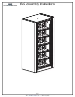
Page 1: ...Ez2 Assembly Instructions Page 1 www StoreMoreStore com 1 855 786 7667 ...

Page 2: ...4 20 x 3 4 Countersink Allen Flat Head Screw 1 4 20 x 1 2 Phillips Pan Head Screw 1 4 20 x 5 8 Phillips Pan Head Screw 3 16 x 3 8 Allen Head Cap Shoulder Screw 10 24 x 1 2 Type F Phillips Pan Head Screw 1 4 20 Flanged Hex Nut 1 4 20 Tinnerman Nut 32 Allen Wrench Not Shown Full Size 32 Allen Wrench Not Shown Full Size 1 4 Diameter Spacer www StoreMoreStore com 1 855 786 7667 ...

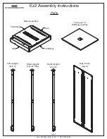
Page 3: ...ructions Parts Base Assembly Top Cover of Rotating Cabinet Side Panel Qty 2 Right Upright w Lock Right Upright w Lock Plug Left Upright Qty 2 Page 3 Front Rear Side Side Front Rear www StoreMoreStore com 1 855 786 7667 ...

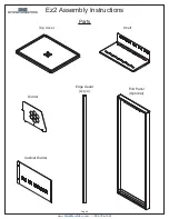
Page 4: ...End Panel Optional Edge Guard Qty 4 Divider Cabinet Divider Page 4 Parts Ez2 Assembly Instructions Top Cover Shelf www StoreMoreStore com 1 855 786 7667 ...

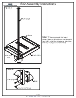
Page 5: ...ach a left upright to the base with two 1 4 20 x 3 4 Flat Countersink Allen Cap Screws see Figure A and Detail B Ez2 Assembly Instructions Page 5 Base Front of Unit Side of Unit 1 4 20 x 3 4 Screw Base Left Upright Left Upright www StoreMoreStore com 1 855 786 7667 ...

Page 6: ...Screws see Figure C and Detail D Step 3 Repeat Steps 1 2 for the rear of the unit Use right upright with lock plug for rear of unit The unit should now look like Figure E Page 6 Right Upright w Lock Base Front of Unit 1 4 20 x 3 4 Screw Base Right Upright w Lock Right Upright w Lock Plug Left Upright Left Upright www StoreMoreStore com 1 855 786 7667 ...

Page 7: ...ock bar into rectangular slot Detail J Rotate lock bar so it is in a vertical position Detail K Maneuver lock bar until short end of hook protrudes through return hole in base Detail K Page 7 Shipping Bolts Rectangular Slot NOTE Any units manufactured after 12 01 2006 will have a new rotating base design Removal of shipping bolts in Step 4 will allow the top part of the rotating base to come loose...

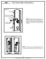
Page 8: ...r and spacer tube attach to lock cam Tighten with 3 32 allen wrench supplied Step 7 Please verify correct positioning of lock components when locked and unlocked Figure M Ez2 Assembly Instructions Page 8 Apply dab of lock adhesive in hole Spacer Lock Bar Upright 3 16 x 3 8 Shoulder Bolt www StoreMoreStore com 1 855 786 7667 ...

Page 9: ...se Base Detail P Side Panel Base Spinning Base Top NOTE Any units manufactured after 12 01 2006 will have a new rotating base design Prior to attaching side panels in Step 8 the top and bottom parts of the rotating base must be properly aligned so that the 10 x 1 2 screws used to attach the side panels can pass through the top part of the rotating base and grip the holes in the bottom part of the ...

Page 10: ...Pan Head Screws to each side panel as shown in Figure S and Detail T Step 11 Position top of rotating cabinet as shown in Figure U with slots aligned with the screws that were just installed Now tighten the screws Page 10 Ez2 Assembly Instructions Detail T 10 24 x 1 2 Screw Top of Rotating Cabinet Side Panel 10 24 x 1 2 Screw Side Panel www StoreMoreStore com 1 855 786 7667 ...

Page 11: ...on Fasten top cover to uprights with a total of eight 10 x 3 8 Phillips Pan Head Screws Step 13 Position and attach cabinet divider using four 1 4 20 x 1 2 Phillips Pan Head Screws and 1 4 20 Nylock Nuts Figure W and Detail X Page 11 Top Cover 10 x 3 8 Screw Cabinet Divider Detail X Cabinet Divider 1 4 20 x 1 2 Screw 1 4 20 Nylock Nut www StoreMoreStore com 1 855 786 7667 ...

Page 12: ...s a small indicator hole can be found next to each standard shelf hole see Detail Z This will allow for equal shelf openings and in most cases it will leave enough space for a posting shelf Leave about an 1 8 gap between head of screw and surface of side panel when fastening screws in next step Ez2 Assembly Instructions Detail Z 10 24 x 1 2 Screw Indicator Hole www StoreMoreStore com 1 855 786 766...

Page 13: ...o mounting screws Figures AA AB then push shelf in and tip it down so rear of shelf hooks on to rear two screws Figure AC Tighten screws Step 16 Repeat Step 15 to install remainder of shelves Page 13 Side Panel Side Panel Side Panel Shelf 10 24 x 1 2 Screw Shelf 10 24 x 1 2 Screw Shelf www StoreMoreStore com 1 855 786 7667 ...

Page 14: ... will attach to each other by using six 1 4 20 x 5 8 Phillips Pan Head Screws and Nuts see Figure AD and Detail AE Units attaching to an end panel will use six 1 4 20 x 5 8 Phillips Pan Head Screws see Figure AD and Detail AF Page 14 End Panel 1 4 20 Nut 1 4 20 x 5 8 Screw 1 4 20 x 5 8 Screw End Panel Should Have Tinnerman Nuts Attached www StoreMoreStore com 1 855 786 7667 ...

Page 15: ... Step 18 To install dividers insert front tab first Figure AG Then insert rear two tabs Figure AH Two dividers per shelf Page 15 Ez2 Assembly Instructions Divider Divider Shelf Shelf www StoreMoreStore com 1 855 786 7667 ...

Page 16: ... Ez2 Assembly Instructions Step 19 Attach edge guards to the four uprights Edge guards attach by simply pressing them on short flange of each upright Detail AK Page 16 Upright Top Cover Edge Gaurd Upright Edge Guard www StoreMoreStore com 1 855 786 7667 ...

Page 17: ... Assembly Instructions Step 20 To level the unit use a 3 16 Nut Driver to adjust the four leveling glides from the access holes in top of base see Detail AN Page 17 Access Hole for Leveling www StoreMoreStore com 1 855 786 7667 ...

Page 18: ...END OF INSTRUCTIONS www StoreMoreStore com 1 855 786 7667 ...

Reviews: