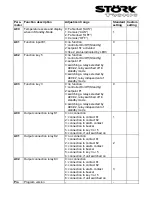
A32: Setpoint display
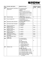
A32=0 indicates the actual value, A32=1 statically indicates the setpoint S1 or S1’ in the display.
Therefore, the current actual value can only be indicated with parameter P0.
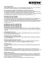
A33: Adjustment of setpoint S1‘ (not available on all types of controllers)
By closing switching input E1, setpoint S1 can be switched to a setpoint S1’. Setpoint S1’ can be
either relative to setpoint S1 or an independent, freely adjustable, control setting.
The setpoint S1’ can only be accessed if input E1 is closed. The setpoint S1’ can only be activated,
if the external input is configured for setpoint change-over (parameter A81=2 or 3).
A40: Hysteresis mode contact K1
A41: Hysteresis mode contact K2
These parameters allow selection as to whether the hysteresis values which are adjustable with
P32, are set symmetrically or one-sided at the respective switching point. At symmetrical
hysteresis, half of the hysteresis’ value is effective below and half of the value above the switching
point. The one-sided hysteresis works downward with heating contact and upward with cooling
contact (see fig. 1 + 2).
A50: Minimum action time contact K1 ”On”
A51: Minimum action time contact K1 ”Off”
A52: Minimum action time contact K2 ”On”
A53: Minimum action time contact K2 ”Off”
These parameters permit a delay in switching on/off the relay in order to reduce the switching
frequency. The adjusted time sets the entire minimum time period for a switching-on or switching-
off phase.
A54: Delay after “Power-on”
This parameter allows a switching-on delay of relays after switching-on the mains voltage. This
delay corresponds with the time set here.
A55: Mutual delay of contacts K1 and K2
This parameter makes a mutual switching-on delay of relays possible, depending on whichever
contact is switched first.
A56: Alarm suppression after "Power-On"
This parameter allows a switching-on delay of the alarm contact after switching on the mains
voltage or setpoint change-over. This delay corresponds with the time set here.
A60: Sensor type
These parameter permits selection of the sensor type, if the needed hardware prerequisites are
available.
A70: Software filter
With several measuring values, it is possible to obtain an average value. This parameter can
determine by how many measured values an average value is to be formed. If a sensor with a very
fast reaction to external influences is used, an average value ensures a calm signal process.
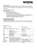
A80: Temperature scale
Indication can be switched between Fahrenheit and Celsius. At conversion, the parameters and
setpoints maintain their numerical value and adjustment range. (Example: A controller with the
desired value of 0°C is switched to Fahrenheit. The new desired value is then interpreted as 0°F,
which corresponds to a temperature of -18°C).
NOTE: Indication limits with °F can be smaller than the actual measuring range!
Summary of Contents for ST710-KHJV.03
Page 2: ......


