background image


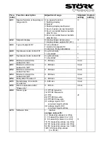
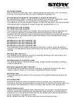
A81: Function E1 

With this parameter function of the ext. input E1 can be set. With A81=0 the E1 is not evaluated. 
With A81=1 the controller is switched to the standby mode. With A81=2 or A81=3 setpoint S1 is 
switched to setpoint S1’ when input E1 is closed. With A81=3 the status of E1 is indicated by LED3 
in the display.  
 

A82: Function „key 5“ (Standby) 
A83: Function „key 3“ 

The following functions are available: 
 

0: the respective key has no function 


1: the controller is switched to standby mode 


2: the key is linked with the function of parameter P1 


3: a relay (indicated with parameter A90-92) can be switched on or off directly with the key. 


    In standby mode the key is locked and the corresponding relay switched off. After  


    restarting the corresponding relay remains switched off 


4: like 3, but the relay is switched despite of


the standby mode. 


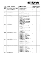
A90: Output connection relay K1 
A91: Output connection relay K2 
A92: Output connection relay K3 

Depending on existing hardware there may not be all output relays. This parameter assigns the 
respective relay to the internal controller outputs, to key 3 or 5, to the alarm contact or the buzzer.  


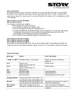
Status messages 
 
Message 

Cause 
 

Error elimination 

“AUS” or “OFF” 

Standby modus, no regulation 

Switch on by key or switching 
entrance 

F1L 

Sensor error,  
short-circuit at sensor F1 

Check sensor 

F1H 

Sensor error,  
open-circuit at sensor F1 

Check sensor 

F3 

Range alarm 


F3L 

Boundary alarm 

Low temperature 

F3H 

Boundary alarm 

High temperature 

_ _ _ 

Key-lock active  
 

Change parameter P19 or A19 

display flashes 

Temperature alarm at too high or too 
low temperature (if activated) see A31 


Buzzer 

Temperature alarm at too high or too 
low temperature (if activated) see A31 

The buzzer function can be switched 
off with the DOWN-key 

EP, display 
flashes 

Data loss at parameter memory 
(Contacts K1 and K2 are switched off) 

If error cannot be eliminated by 
switching on/off, the controller must be 
repaired 


Summary of Contents for ST710-KHJV.03

Page 1: ...controller with alarm three point controller with alarm contact two stage controller with alarm contact three stage controller Beside the standby key there is a second key to set functions which can be variously parametered Sensor PTC Range 50 150 C Front size 84mm x 42mm Panel cut out 67 5mm x 31 5mm Tightness front IP65 Connector plug and socket Power supply 12 24V 16 36V ...

Page 2: ......

Page 3: ...s see parameter A82 Standby mode direct switching of a contact setpoint P1 First control level Parameter setting of the control setpoint If none of the keys is pressed the display indicates the actual value of the temperature Pressing the SET key the setpoint shows on the display If the setpoint is to be changed the SET key is to be kept pressed while adjusting the setpoint with the keys UP and DO...

Page 4: ...position takes place automatically if no key is pressed for 60 seconds Para meter Function description Adjustment range Standard setting Custom setting P0 Actual value P1 Setpoint or DeltaW P4 P5 99 9 99 9 K 10 0 C K P2 Hysteresis contact K1 0 1 99 0 K 1 0 K P3 Hysteresis contact K2 0 1 99 0 K 1 0 K P4 Control range limitation minimum setpoint 99 C P5 99 C P5 Control range limitation maximum setpo...

Page 5: ...sis works downward with heating contact and upward with cooling contact At symmetrical hysteresis half of the hysteresis value is effective below and half of the value above the switching point see fig 1 and 2 Fig 1 Heating controller one sided hysteresis Fig 2 Cooling controller symmetrical hysteresis P4 Control range limitation minimum setpoint P5 Control range limitation maximum setpoint The ad...

Page 6: ... one sided inwardly and at range alarm outwardly see fig 3 6 P32 Hysteresis alarm circuit Hysteresis is set one sided at the adjusted limit value It becomes effective depending on alarm definition see fig 3 6 Fig 5 Boundary alarm alarm contact invers A30 4 limits relative A30 5 limits absolute Fig 6 Range alarm alarm contact invers A30 6 limits relative A30 7 limits absolute Fig 3 Boundary alarm a...

Page 7: ... mode contact K1 0 heating contact 1 cooling contact 0 A2 Switch mode contact K2 0 heating contact 1 cooling contact 1 A3 Function of contact K1 at sensor error 0 relay off 1 relay on 0 A4 Function of contact K2 at sensor error 0 relay off 1 relay on 0 A5 Selection setpoint 2 or DeltaW 0 operation with setpoint 2 1 operation with DeltaW 1 A8 Display mode all parameter indications are presented in ...

Page 8: ...ided 1 A50 Minimum action time contact K1 On 0 600 sec 0 sec A51 Minimum action time contact K1 Off 0 600 sec 0 sec A52 Minimum action time contact K2 On 0 600 sec 0 sec A53 Minimum action time contact K2 Off 0 600 sec 0 sec A54 Delay after Power on 0 600 sec 0 sec A55 Mutual delay of contacts K1 and K2 0 600 sec 0 sec A56 Alarm suppression after Power On 0 60 min 0 min A60 Sensor type 11 PT100 tw...

Page 9: ... P1 3 switching a relay selected by A90 92 relay switched off in standby mode 4 switching a relay selected by A90 92 relay independent of standby mode 0 A90 Output connection relay K1 0 no connection 1 connection to contact K1 2 connection to contact K2 3 connection to alarm contact 4 connection to buzzer 5 connection to key 3 or 5 6 connection if unit switched on 1 A91 Output connection relay K2 ...

Page 10: ...ed by it and both indicated in the display and applied for regulation A10 Indication value for lower value linear analogue input A11 Indication value for upper value linear analogue input Only relevant if the controller is programmed for a voltage input 0 10V linear or a current input 4 20mA linear These parameters allow scaling of the linear analogue input The value to be indicated for the lower ...

Page 11: ...order to reduce the switching frequency The adjusted time sets the entire minimum time period for a switching on or switching off phase A54 Delay after Power on This parameter allows a switching on delay of relays after switching on the mains voltage This delay corresponds with the time set here A55 Mutual delay of contacts K1 and K2 This parameter makes a mutual switching on delay of relays possi...

Page 12: ...ection relay K1 A91 Output connection relay K2 A92 Output connection relay K3 Depending on existing hardware there may not be all output relays This parameter assigns the respective relay to the internal controller outputs to key 3 or 5 to the alarm contact or the buzzer Status messages Message Cause Error elimination AUS or OFF Standby modus no regulation Switch on by key or switching entrance F1...

Page 13: ...see A81 Outputs K1 Relay normally open contact 8 1 5 A 250V function see A90 K2 Relay normally open contact 8 1 5 A 250V function see A91 K3 Relay normally open contact 6 0 5 A 250V function see A92 Additional buzzer 85dB Power supply 12 24 V AC 50 60 Hz or 16 36V DC power consumption max 4 VA Connectors 12 pole plug and socket spacing 5 0 mm for cable up to 2 5 mm Ambient conditions Storage tempe...

Reviews: