background image

Environment

Warning

The operations described in this document must only be performed by operators who have been
trained in the maintenance of products containing electronic cards, and having been duly
instructed by the user to do so.

Before performing any intervention, the operator must ensure in particular that:

l

The product is physically disconnected from the mains power supply,

l

All precautions have been taken to guarantee an ESD-safe (ElectroStatic Discharge)
environment.

Recycling

If the storage medium is approaching the end of its life cycle, it is the operator’s duty to comply
with existing recycling regulations.

Required tools

l

A set of Phillips screwdrivers,

l

A small flat screwdriver,

l

A set of spanners for hex spacers.

SNS - TECHNICAL NOTE

SECURE RETURN OPTION

Page 5/28

sns-en-secure_return_option_technical_note - 10/10/2020

Summary of Contents for SN150

Page 1: ...STORMSHIELD NETWORK SECURITY SECURE RETURN OPTION Product concerned SNS 3 11 and higher versions SNS 4 1 and higher versions Document last update October 10 2020 Reference sns en secure_return_option_...

Page 2: ...Dismantling 9 Assembling 9 SN510 SN710 and SN910 10 Dismantling 10 Assembling 11 SN900 12 Dismantling 12 Assembling 13 SN2000 and SN3000 14 Dismantling 14 Assembling 15 SN2100 and SN3100 16 Dismantlin...

Page 3: ...SNi40 25 Dismantling 25 Assembling 27 SNS TECHNICAL NOTE SECURE RETURN OPTION Page 3 28 sns en secure_return_option_technical_note 10 10 2020...

Page 4: ...m for confidentiality reasons This document sets out the phases associated with this operation for products in the Stormshield Network range For products in the NETASQ range please refer to the Techni...

Page 5: ...product is physically disconnected from the mains power supply l All precautions have been taken to guarantee an ESD safe ElectroStatic Discharge environment Recycling If the storage medium is approac...

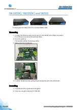
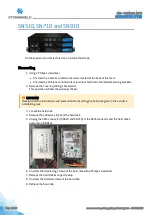
Page 6: ...g the small flat screwdriver remove the adhesive strip by scraping lightly at it 4 Unlock the metal cover by sliding it a few millimeters towards the rear of the product 5 Open up the cover all the wa...

Page 7: ...Flash module 4 Unscrew the fastening screw of the Flash module with a Philips screwdriver 5 To extract the flash module pull it gently perpendicular to the motherboard Assembling 1 Ensure that the sc...

Page 8: ...the warranty sticker 2 Open the appliance This operation will tear the warranty sticker 3 Remove the strip of white glue 4 To extract the flash module pull it gently and perpendicular to the motherboa...

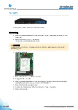
Page 9: ...A connector 6 Unscrew the 4 fastening screws of the hard disk with a Philips screwdriver 7 Remove the hard disk support setup 8 Unscrew the 4 lateral screws of the hard disk 9 Retrieve the hard disk A...

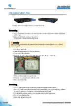
Page 10: ...Closely follow the instructions and precautions for handling the hard disk given in the vendor s installation guide 3 Locate the hard disk 4 Remove the adhesive strip from the hard disk 5 Unplug the...

Page 11: ...the free ring terminal of the cable connecting the support hard disk setup to the chassis 3 Check that the 4 lateral screws of the hard disk remain outside the chassis 4 Put the cover and fastening br...

Page 12: ...hard disk given in the vendor s installation guide 3 Locate the hard disk 4 Remove the adhesive strip from the hard disk 5 Unplug the SATA connector 6 Using the Phillips screwdriver unscrew the 4 fast...

Page 13: ...to fasten the free ring terminal of the cable connecting the support hard disk setup to the chassis 3 Check that the 4 lateral screws of the hard disk remain outside the chassis 4 Put the cover back i...

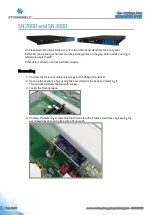
Page 14: ...smantling 1 Unscrew the 9 black countersunk screws with a Philips screwdriver 2 Open up the appliance by pushing the cover towards the back and removing it This operation will tear the warranty sticke...

Page 15: ...uire the crossbar to be dismantled Assembling 1 Ensure that the screw of the Flash module remains outside the chassis 2 Put the cover back in place 3 Push it forward 4 Close the chassis back up using...

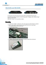
Page 16: ...rnal flash module Dismantling 1 Unscrew the 13 black countersunk screws of the upper cover with a Philips screwdriver 2 Open up the appliance by pushing the cover towards the back and removing it This...

Page 17: ...ct it by pulling it gently and perpendicular to the motherboard Assembling 1 Put the cover back on 2 Push it forward 3 Close the chassis back up using the 13 screws SNS TECHNICAL NOTE SECURE RETURN OP...

Page 18: ...the cover of the chassis with a Philips screwdriver l 2 lateral countersunk screws on the rear of the product l 2 pan head machine screws on the rear panel 2 Open up the appliance by pushing the cover...

Page 19: ...SSD by removing the 4 countersunk screws under the SSD Assembling 1 Place the metal plate back into its notches 2 Push it towards the front of the chassis 3 Fasten it using the 4 screws 4 Ensure that...

Page 20: ...ernal flash module Dismantling 1 Unscrew both of the thumbscrews that fasten the top cover located on the rear panel of the SN6100 2 Open up the appliance by pushing the cover towards the back This op...

Page 21: ...rew of the flash module back in its spacer Assembling 1 Put the cover back on 2 Push it forward 3 Close the chassis back up using the 2 turnscrews SNS TECHNICAL NOTE SECURE RETURN OPTION Page 21 28 sn...

Page 22: ...the 2 black screws that hold the DIN rail bracket in place 3 Remove the bracket 4 Unscrew the 14 black screws found on the appliance 5 Open the appliance SNS TECHNICAL NOTE SECURE RETURN OPTION Page 2...

Page 23: ...silver fastening screws from the metal plate 8 Take off the metal plate 9 Unscrew the 5 gold colored spacers with a 5mm hex socket SNS TECHNICAL NOTE SECURE RETURN OPTION Page 23 28 sns en secure_ret...

Page 24: ...move the second part of the motherboard by pulling gently and vertically 13 Remove the TPM Trusted Platform Module by pulling gently and vertically Assembling Re assemble the product by following the...

Page 25: ...move the warranty sticker 2 Unscrew the 4 silver screws that hold the DIN rail bracket in place 3 Remove the bracket SNS TECHNICAL NOTE SECURE RETURN OPTION Page 25 28 sns en secure_return_option_tech...

Page 26: ...4 Unscrew the 5 black screws found on the appliance 5 Rotate the upper section SNS TECHNICAL NOTE SECURE RETURN OPTION Page 26 28 sns en secure_return_option_technical_note 10 10 2020...

Page 27: ...support 8 Unscrew the fastening screws from the hard disk 9 Remove the hard disk Assembling Re assemble the product by following the same steps to dismantle it in reverse order SNS TECHNICAL NOTE SEC...

Page 28: ...documentation stormshield eu All images in this document are for representational purposes only actual products may differ Copyright Stormshield 2020 All rights reserved All other company and product...

Reviews: