Tel: +44 (0) 1279 419913
www.stortech.co.uk
Whilst every effort has been made to ensure the
accuracy of the information provided, no liability can
be undertaken for any errors or omissions. All
dimensions stated in this document are approximate.
Stortech Electronics Ltd reserves the right to alter the
specifications and introduce changes without prior
notice. © Stortech Electronics 2017
MDVR800_Quick Guide 0507 2017
MDVR800 Series
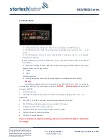
2.1 Back Panel
1
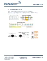
. Video & Audio Input interface, 1-4 Channels or 1-8 Channels, with DC 12V output:
2.
16 PIN Extension Port, With Video & Audio output interface alarm input & output serial
port etc.
3.
24 PIN Extension Port, With alarm input & output serial port etc. For more detailed
definitions see addenda.
4.
RJ45 Ethernet port, with print serial port, Can only connect 4PIN net cable when connect
network cable.
5.
Power Input Voltage DC 8-36V, Red cable connect power positive, Black cable connect power
negative; Yellow line ACC signal cable.
6.
3G/4G
7.
WIFI
8.
GPS Antenna Port
;
9.
VGA high definition output port.(Analog output port is standard definition output);
Attention:
Audio/Video analogue output port is inside the device 16PIN PANEL port When connecting a
network cable directly to the network port, only use a
4PIN RJ45 definition cable
,
otherwise it will
damage the MDVR.
•
[DC-IN] Power port
•
Red cable connect power positive, black cable connect power negative, yellow line ACC
signal cable
•
[AV1-AV4] 1-4 CH Video and Audio input interface include DC 12V output
•
[AVOUT] Video and Audio output interface, include DC 12V output
•
[GPS] Built-in GPS module antenna interface
•
[3G] Built-in wireless communication module antenna interface
•
[SENSOR] Extension Function interface
•
[VGA] Video output interface
If you need timed or ignition recording, please connect the ACC cable to the vehicle
ACC supply


