Whilst every effort has been made to ensure the
accuracy of the information provided, no liability can
be undertaken for any errors or omissions. All
dimensions stated in this document are approximate.
Stortech Electronics Ltd reserves the right to alter the
specifications and introduce changes without prior
notice. © Stortech Electronics 2018
Tel: +44 (0) 1279 419913
www.stortech.co.uk
MDVR808 Quick Guide 21052018
MDVR808 Series
3.
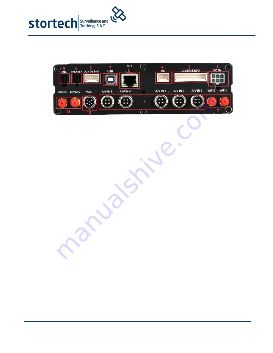
Back Panel
1. Power Input interface. Input voltage is DC 6-36V. Red cable connects positive power. Black cable
connects negative power. Yellow line ACC signal cable.
2. Wi-Fi antenna interface supports double Wi-Fi.
3. 30 PIN Extension Port. Including 1st-10th alarm input, RS232,RS485 interface, detailed definition see
Annex.
4. 10PINExtension Port, including 11th-16th alarm input, support 4channel alarm output interface.
5. Video & Audio Input interface, 1-8Channels support AV input with DC 12V output.
6. RJ45 Ethernet port. This is used for wired network connection.
7. USB data port. This is used for data backup.
8. Speaker output interface. External speakers etc.
9. Microphone input interface. External microphone etc.
10. VGA HD output interface.
11. GPS antenna interface.
12. 3G/4G antenna interface.
Attention:
The Audio/Video analogue output port is inside the device 16PIN PANEL port
When connecting a network cable directly to the network port, only use a
4PIN RJ45 definition cable
,
otherwise it will damage the MDVR.
[DC-IN] Power port
Red cable connect power positive, black cable connect power negative, yellow line ACC
signal cable
[AV1-AV4] 1-4 CH Video and Audio input interface include DC 12V output
[AVOUT] Video and Audio output interface, include DC 12V output
[GPS] Built-in GPS module antenna interface
[3G] Built-in wireless communication module antenna interface
[SENSOR] Extension Function interface
[VGA] Video output interface
If you need timed or ignition recording, please connect the ACC cable to the vehicle ACC supply


