background image

Whilst  every  effort  has  been  made  to  ensure  the 
accuracy of the information provided, no liability can 
be  undertaken  for  any  errors  or  omissions.  All 
dimensions stated in this document are approximate. 
Stortech Electronics Ltd reserves the right to alter the 
specifications  and  introduce  changes  without  prior 
notice. © Stortech Electronics 2018


Tel: +44 (0) 1279 419913


www.stortech.co.uk


MDVR808 Quick Guide 21052018


MDVR808 Series


4.


DVR Wiring Installation Introduction 

Please ensure to read this fully before installation and first usage. 

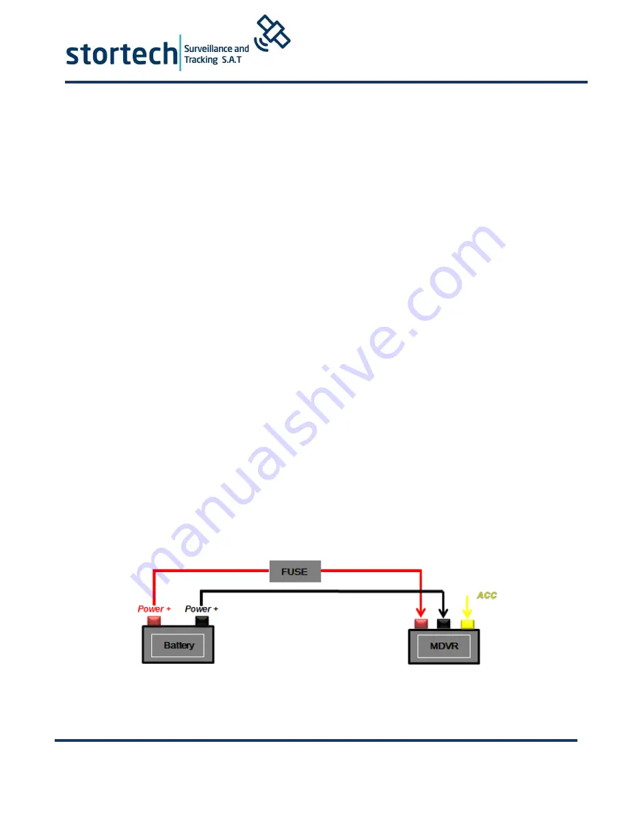
Device Power Connection:


Only connect the MDVR to the vehicle power supply. The power for cameras and 
monitors are all supplied by MDVR via aviation connectors and its built-in DC 12V 
output. 


Use the ignition switch to control the video recorder delay timer operation.


Red cable must connect to the positive of the vehicle storage battery.  Black  cable 
connects to the negative. Yellow cable must connect to an independent ignition 
switch (ACC).


Switch Connection (Indoor test).


Red  cable  and  yellow  cable  together  connect  power  positive  of  the  car  storage 
battery, whilst black cable connect negative.


The Camera connects via AV IN.  
The Monitor connects via BNC connector of AV out of PANEL.  
If it is not a standard aviation connector, please use the aviation conversion line. 
Black  side  is  DC  12V  output.  White  side  is  Audio  output.  Yellow  side  is  Video 
output.


★ 

Use the ignition switch or (ACC) to control the MDVR record delay time  operation.


Summary of Contents for MDVR 808

Page 1: ...taken for any errors or omissions All dimensions stated in this document are approximate Stortech Electronics Ltd reserves the right to alter the specifications and introduce changes without prior not...

Page 2: ...m the vehicle supply to the MDVR all power cables must be able to withstand 5 Amps or more Install the equipment in the dry and avoid damp drips water spray etc To extend the life of the equipment ple...

Page 3: ...elete Button Return to the preview picture or previous screen Enter button button for setting system parameters Direction Key up down left right Display system info under monitoring mode Rewind button...

Page 4: ...uld be inserted straight into slot Notch should be inward with metal contacts upwards 5 HDD box Press the left button then you can open the hard disk box door and insert into 2 5 inch hard drive 6 SIM...

Page 5: ...ace 1 8Channels support AV input with DC 12V output 6 RJ45 Ethernet port This is used for wired network connection 7 USB data port This is used for data backup 8 Speaker output interface External spea...

Page 6: ...s and monitors are all supplied by MDVR via aviation connectors and its built in DC 12V output Use the ignition switch to control the video recorder delay timer operation Red cable must connect to the...

Page 7: ...Quick Guide 21052018 MDVR808 Series 5 Main Configuration Instructions SIM card dial up parameters should be set in 3 4G Setup Customers can consult APN and other related parameters from SIM card opera...

Page 8: ...lter the specifications and introduce changes without prior notice Stortech Electronics 2018 Tel 44 0 1279 419913 www stortech co uk MDVR808 Quick Guide 21052018 MDVR808 Series The following shows the...

Page 9: ...ter the specifications and introduce changes without prior notice Stortech Electronics 2018 Tel 44 0 1279 419913 www stortech co uk MDVR808 Quick Guide 21052018 MDVR808 Series Video Recording Setting...

Page 10: ...r the specifications and introduce changes without prior notice Stortech Electronics 2018 Tel 44 0 1279 419913 www stortech co uk MDVR808 Quick Guide 21052018 MDVR808 Series When Double SD cards or HD...

Page 11: ...onics Ltd reserves the right to alter the specifications and introduce changes without prior notice Stortech Electronics 2018 Tel 44 0 1279 419913 www stortech co uk MDVR808 Quick Guide 21052018 MDVR8...

Page 12: ...antle 4 screws in the side and underside as shown in Figure 1 2 Install 4 screws on 2 5inch hard disk Remove the hard disk box from one side bracket as shown in Figure 2 3 First connect SATA flat cabl...

Page 13: ...mat format HDD SD card If not recording check Timed Recording mode if this is set to yes it will not record all of the time Also check HDD light is on GPS related FAQ Q I have GPS but GPS coordinate i...

Page 14: ...for any errors or omissions All dimensions stated in this document are approximate Stortech Electronics Ltd reserves the right to alter the specifications and introduce changes without prior notice S...

Reviews: