background image

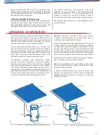
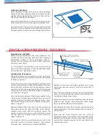
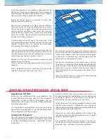
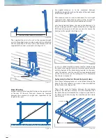
Strap trimmed to 
shorter length

Strap fixed with 
two Hex head 
self-drilling screws

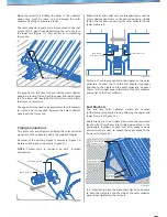
600

mm

600

mm

700

mm

Figure 8

Figure 9

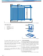
Roof Mount Tilt Kit Preparations

Measure the available mounting area to confirm frame 
orientation. Solar collectors are to be mounted in a 
portrait orientation only.

Determine the best orientation of the array to satisfy the 
following requirements:

• 

Requirements of equator direction and tilt angle.

• 

Maximise space for the number of solar collectors.

• 

Mounting frame attachment to roof rafters and 
battens.

• 

Tilt frame bracing points.

• 

Roof obstructions, chimneys, skylights, etc.

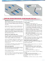
The rail length can be calculated using the following 
equation.
A = Width of the Solar Collector (700mm)
Q= Number of solar panels to be mounted to the rail
RAIL LENGTH = (QxA) + (50x2) + ((Q-1) x24) 
Example;
RAIL LENGTH = (4x700) + (50x2) + ((4-1)x24) = 2972mm 

The roof members must be inspected and be of suitable 
type and in sound condition.

Layout Rules

• 

Maximum roof height limited to 10m.

• 

Connections to be made down to existing roof 
structure, through the roof batten into the rafter, or 
at a maximum spacing of 150mm from the rafter. 
It is the builder’s responsibility to reinforce the 
connection between the roof batten and the rafter.

• 

Maximum overhang of the rail from the bracket 
attachment to the house rafter is 400mm.

• 

Minimum of 2 screws per bracket into the house roof 
for timber and steel frame housing. Refer to note for 
additional information regarding connection of roof 
mount tilt frames in Region B.

• 

The maximum distance between mounting brackets 
is 1500mm in Region A, 1200mm for timber trusses 
and 1500mm for steel trusses in Region B.

NOTE:

 In Region B, Terrain Category 1, where roof mount 

tilt kits are attached to steel framing, the steel framing 
rafter spacing is limited to maximum 1200mm.

Regulations & OH&S

Before starting construction and installation the installer 
should ensure they have read the “Important Information” 
section of these instructions and are familiar with 
the relevant standards, OH&S regulations and safety 
precautions.

Double check all dimensions, levels and bolting locations 
before cutting, screwing or bolting structural members. 

It is the builder’s responsibility to ensure the existing 
house structure is adequate to take the additional loads 
of the SolarCore

TM

 Hot Water System, and that the persons 

erecting the structure have had some previous building 
experience because some modifications to the existing 
house structure are required.

Attach to an Existing Structure

The builder or council is to ensure the existing house/
structure is limited to a roof height of 10m, and of a 
suitable structural integrity that complies with all the 
relevant Australian Building codes and standards. 

For more information regarding the suitability of the 
house structure to accommodate the solar collectors 
and mounting frame, consult a structural engineer or a 
building authority. 

It is the builders responsibility to ensure that the existing 
house roof structure is strengthened correctly.

Planning Preparation

The portrait orientation of the solar collector array is to 
be mounted facing the equator and tilted at an angle 
equal to the sites latitude, from horizontal. 

The solar collectors are not to be partially or fully shaded 
by surrounding obstructions.

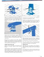
All mounting brackets must be fixed to the existing roof 
rafter, or at a maximum distance of 150mm from the 
rafter, through the roof batten.

INSTALLATION PROCEDURE - ROOF MOUNT TILT KIT

Summary of Contents for Solarcore G21520L666VE

Page 1: ...al Occupational Health Safety regulations Wind Regions Covered Flat Mount Kit Region A N1 N2 N3 Region B N1 N2 N3 N4 Checked to AS NZS 1170 2 2002 and AS4055 2006 Tilt Mount Region A N1 N2 N3 Maximum...

Page 2: ...e tank During extended absences in summer it is advisable to cover the solar collector to avoid overheating the system and excessive dumping of hot water from the P TR valve Hydrogen Gas Warning For v...

Page 3: ...ect heat from sunlight during cool windy or even overcast weather The heat is rapidly transferred to water passing through copper pipes inside the evacuated glass tubes A pump circulates the heated wa...

Page 4: ...NUT Qty 4 or 6 ANGLE BRACE M10 NUT Qty n a M10 SOCKET BOLT Qty n a M10 WASHER Qty n a ANGLE BRACE SHORT FRAME RAIL RAIL NUT TILT BRACKET CGI ROOF BRACKET FLAT ROOF BRACKET TILT MOUNT CIRCULATION PUMP...

Page 5: ...Litre Number of Collectors 2 3 3 Continuous Flow Gas Boost Size L min 20 26 20 26 20 26 Weight Cylinder Empty kg 88 95 Connections All connections parallel pipe threads of whitworth form Solar Flow a...

Page 6: ...Up Time 45 C Rise 2hrs 55min 4hrs 40min Recovery Rate Litres per Hour 45 C Rise 69 69 Weight Cylinder Empty kg 88 103 Connections All connections parallel pipe threads of whitworth form Solar Flow an...

Page 7: ...SX 65 C 65 C Switch on Temp Reheating TO 40 C not used N A Switch off Temp Reheating TF 40 C not used N A Freeze Protection Function Collector AF 1 freeze prot function active N A Operating Mode MM 4...

Page 8: ...f true North is acceptable Mounting the solar collector on a North East or North West facing roof will only reduce solar collector efficiency by approximately 5 Solar Collector Inclination The ideal i...

Page 9: ...e hook on the bottom stainless steel straps with the markings Fasten the bottom stainless steel straps to the roof battens using two hex head self drilling wood or metal screws as shown in Figure 6 It...

Page 10: ...er and seal the opening of the orifice with a small amount of silicon Run the hot temperature sensor leads under a tile into the roof space and down to the solar pump controller but do not connect at...

Page 11: ...In Region B Terrain Category 1 where roof mount tilt kits are attached to steel framing the steel framing rafter spacing is limited to maximum 1200mm Regulations OH S Before starting construction and...

Page 12: ...he batten and roof sheet using two M6 TS self drilling screws as noted in the Layout Rules within this section of these instructions A protective anti corrosion barrier must be installed between dissi...

Page 13: ...and second frame rail at one end to stop the frame from tipping thereby keeping a square alignment Upright Rail Positioning Position a series of roof brackets corresponding to the front row at the di...

Page 14: ...led distance is to be measured between neighbouring upright rails on the outer of the roof mount tilt kit frame Figure 18 This measurement is used to determine the cut length required of the angle bra...

Page 15: ...de of the solar collector panel when tightening the rail nuts When all inlet and outlet nuts are threaded firmly and the solar collector panels are in the desired position tightly fasten the rail nuts...

Page 16: ...hed power point IMPORTANT NOTE The controller is factory programmed to the correct settings These settings must not be altered Toensurefrostprotectionthepowermustremainconnected to the electronic cont...

Page 17: ...Location The hot water storage tank should be located as close as possible to the most frequently used hot water outlets to minimise water wastage and heat loss Also consider that the solar collector...

Page 18: ...n wear of the P TR valve Approved pressure limiting valves rated at 500kPa must be fitted if the mains water supply pressure exceeds 500kPa A combination non return isolating valve and strainer is fit...

Page 19: ...pansion control valve and tee to the cold water inlet connection at the bottom of the hot water storage tank A pressure limiting valve is required if the water supply pressure exceeds 500kPa Fit the s...

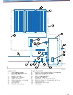
Page 20: ...8 Solar collectors Supplied by Installer 2 DN15 Solar return pipe insulation connections 5 DN20 copper tube 20mm thick insulation connections 6 Gas supply pipe Isolating valve Disconnection union fitt...

Page 21: ...external installation For external installation the hot water storage tank should be mounted on a concrete base at least 50 mm thick in accordance with AS NZS 3500 4 clause 4 5 3 or on well seasoned...

Page 22: ...connection details The installation of the electric boosted Stratco SolarcoreTM hot water system is now complete Follow the commissioning procedure carefully to ensure the electric boosted solar hot...

Page 23: ...e limiting valve 9 DN15 Water supply pipe connections 10 DN15 Solar flow pipe insulation connections 17 Tempering valve 18 Hot water non return valve 19 240V Power Supplied in Kit 1 Hot temperature se...

Page 24: ...red green to show the pump is running Press the button to exit the settings menue until TC and TS are shown in the display OUTDOOR CONTROLLER Press and hold the pump button The circulating pump shoul...

Page 25: ...he power points for the electronic controller circulating pump or the water supply For gas boosted systems switch off the power points for the gas booster To ensure frost protection do not switch off...

Page 26: ...nk Check mains water isolating valve to inlet of hot water storage tank is open Check mains water isolating valve at water meter is open Check water flow at a cold water tap and contact the water supp...

Page 27: ...the solar collector should be checked for vacuum every 5 years This is indicated by a silver coating at the bottom of the glass tube If the bottom of the glass tube has turned white or clear the glas...

Page 28: ...d systems or isolate power supply to the heating element at the mains for electric boosted systems Close the isolating valve on the cold water supply to the hot water storage tank Disconnect the elbow...

Reviews: