background image

Ecotech (Low Input) Issue 1.2 28/06/01

 Page 4 of 7

Leak test & pressure test

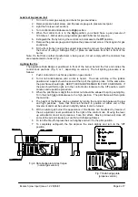
1.  Turn on the main gas supply and check for gas soundness.
2.  Remove pressure test screw, and fit pressure gauge to pressure test point.
3.  Light the fire (see next section).
4.  Turn control knob anticlockwise to 

High

 position.

5.  When the control knob is in the 

High

 position, you should have a gas pressure of

19.0mbar ± 1.0mbar when using natural gas and 36.5mbar for propane.

6.  Extinguish the fire by turning the control knob clockwise to the 

Off 

position.

7.  Remove the pressure gauge and replace the pressure test screw. Check again for gas

soundness.

8.  Fit the front fret by hooking the support lugs at each end over the slotted front plate on

the burner (if using a Straxgas fret), or place an alternative front fret in front of the
burner.

Note: If a fret from another manufacturer is being used, it must comply with the minimum free
area requirements shown in Fig. 2.

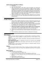
Lighting the fire

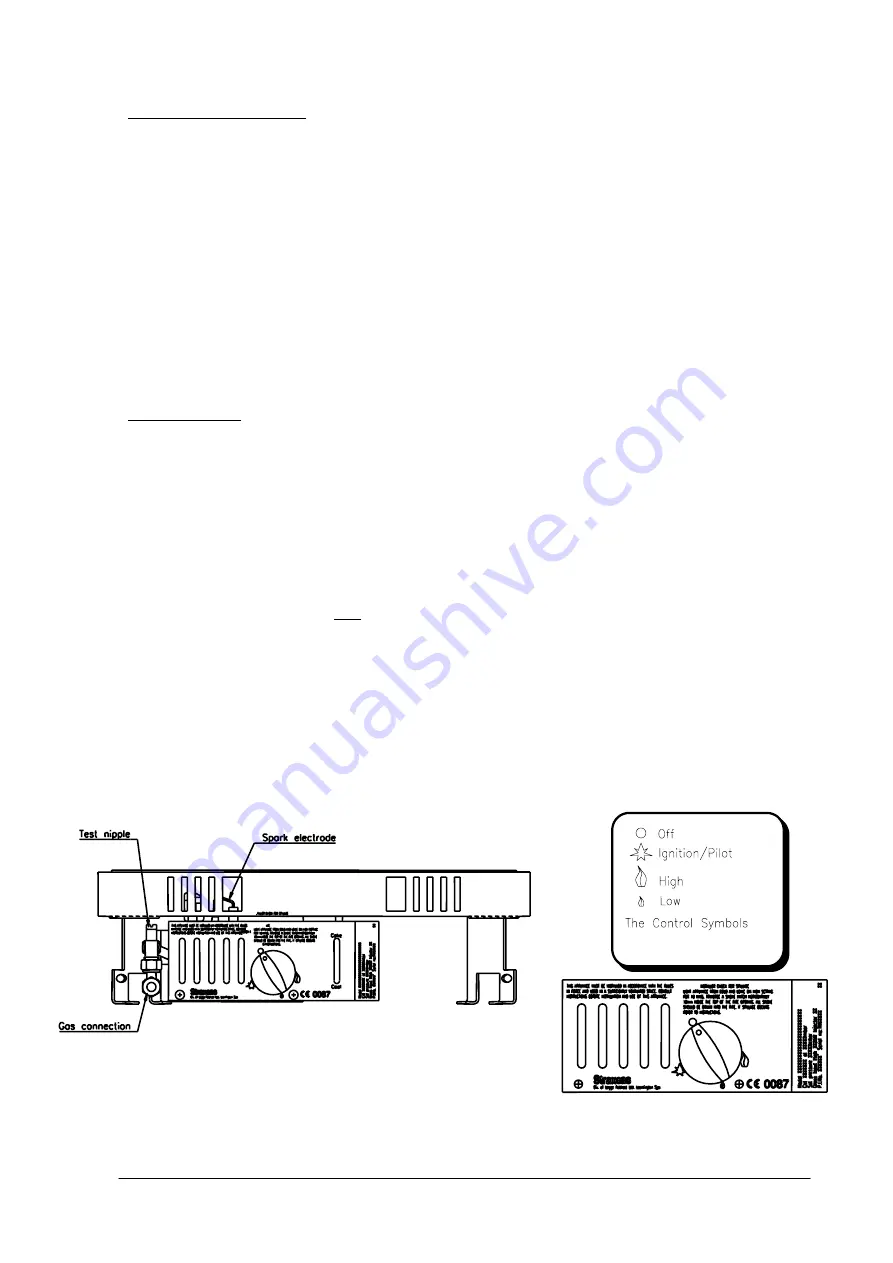
The appliance Data Badge is positioned in front of the burner behind the fret and carries the
control knob positions (Fig. 6 or 7, depending on version). The full lighting procedure is as
follows:

1.  Push control knob in as far as possible on gas control.
2.  Turn knob anticlockwise until a click is heard.  The knob will stop at the ignition

position and a spark should be seen at the tip of the ignition probe.  At the same time
the pilot flame should light.  KEEP THE KNOB PRESSED IN FOR 10 SECONDS.  If
the pilot should fail to light, turn the control knob clockwise to the 'off' position, wait 3
minutes and repeat the procedure.

3.  When the pilot flame is alight the control knob should be allowed to spring out slightly.

Turn the knob fully anticlockwise to the high position.  The pilot flame will then ignite
the main fire.

4.  The height of the flames can be adjusted by turning the control knob between the low

and high positions.  Note that the knob 'latches' in position at either end of this
movement and must be pushed in slightly before it can be turned.

5.  With a natural gas burner the appearance of the flames can be altered by means of

the air adjustment lever positioned to the right of the control knob.  Moving the lever
up will admit more air and produce a 'coke fire' effect.  Moving it down will close off
some of the air and simulate a 'coal fire' with flickering flames.

6.  To turn the fire off, depress the knob slightly and turn it to the pilot position.
7.  To completely extinguish the fire depress the knob slightly and turn to the 'Off'

position.

Fig. 6 Data badge plate & test nipple

(natural gas version)

Fig. 7 Data badge plate

(propane version)

Summary of Contents for 16 Ecotech

Page 1: ... Consolidated Regulations issued by the Scottish Development Board Gas Safety Installation and Use Regulations Failure to install this appliance correctly could lead to prosecution and render the guarantee invalid Attention is drawn to the latest edition of the following standards BS1251 Specifications of open fireplace components BS5440 Part 1 Specification for installation of flues BS5440 Part 2...

Page 2: ...ce with BS 5440 Part 1 Clearances If a shelf is to be fitted above the fire perhaps as part of a surround it must be positioned a minimum of 1m 39in above the top of the hearth and project no more than 200mm 8in from the front plane of the opening Combustible material such as wood may be fitted to within 100mm 4in of either side of the opening so long as it projects no more than 100mm 4in from the...

Page 3: ...s burner should be located as shown in Fig 3 Locate the burner centrally in the opening Securely anchor the burner in the correct position using the screws and plastic plugs supplied holes are provided in the front feet of the burner for this purpose Assembly 1 Connect the gas supply to the inlet elbow 2 The ceramic components are fragile and should be handled with care Refer to Figs 4 and 5 for p...

Page 4: ... control 2 Turn knob anticlockwise until a click is heard The knob will stop at the ignition position and a spark should be seen at the tip of the ignition probe At the same time the pilot flame should light KEEP THE KNOB PRESSED IN FOR 10 SECONDS If the pilot should fail to light turn the control knob clockwise to the off position wait 3 minutes and repeat the procedure 3 When the pilot flame is ...

Page 5: ...ppliance is fitted with an oxygen depletion sensor incorporated into the pilot body Should the fire repeatedly extinguish itself the cause should be sought and remedied as this may indicate spillage into the room of combustion products 4 Indicate the tie on warning label which the customer must remove and read 5 Advise the user that any smell given off by the appliance will clear away after a litt...

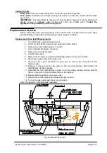
Page 6: ...y by isolation cock 2 Lift off the front fret and remove the coals and ceramic blocks 3 Remove 2 screws holding burner to hearth 4 Undo multidirectional gas connection 5 Remove burner from fireplace 6 Pull off control knob 7 Remove the 2 screws securing the Data Badge plate and remove the plate 8 Disconnect ignition lead to the igniter unit 9 Disconnect all 3 gas connections to gas valve as well a...

Page 7: ...burner 4 Pull off connector on the base of the igniter probe 5 Remove 2 screws on the burner and remove ignition unit complete 6 Fit new pilot assembly and reassemble in reverse order 7 Turn on the gas supply and check for soundness 8 Check operation of ignition system NOTE No liability can be accepted unless this product has been installed and operated strictly in accordance with these manufactur...

Reviews: