5
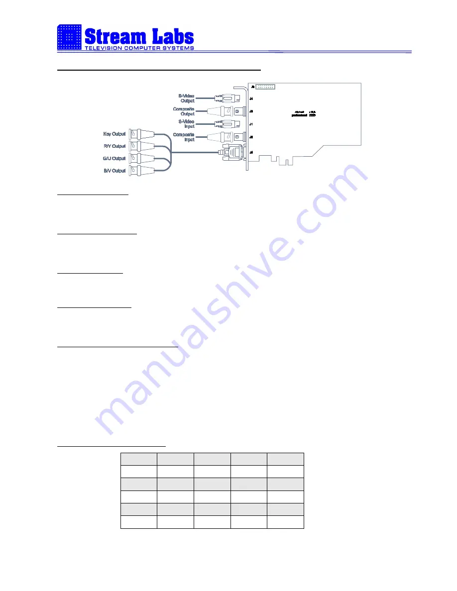
Description of connectors and schema for wiring
S-Video Output (J4):
Thru connector miniDIN-4 video signal in S-Video (Y/C) format is out.
Composite Output (J3):
Thru connector BNC composite video signal is out.
S-Video Input (J2):
Thru connector miniDIN-4 video signal in S-Video (Y/C) format is in.
Composite Input (J3):
Thru connector BNC composite video signal is in.
YUV+Key/RGB+Key Output: (J6):
15-n pin connector D-SUB, which allows connecting VGA cable with BNC outputs Y/G, Cr/R, Cb/B
(green, red and blue, correspondingly) and Key signal (yellow).
During analog overlay, only computer’s graphics is being outputted thru 15-n pin connector. During
digital decoding/coding an output is identical to the main output.
Cable with additional connectors is not a part of a standard package and is being supplied separately.
15-n pin connector D-SUB (J6):
1
2
3
4
5
R/Cr
G/Y
B/Cb
-
-
6
7
8
9
10
Ground
Ground
Ground
-
Ground
11
12
13
14
15
-
-
Key
-
Relay


