11
Assembly
Flue / mounting the air regulation units
Mounting the induced draft fan
Electrical / Water connection / heating connections
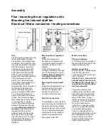
Flue
The flue must be checked by the
responsible master chimney
sweep before the heating boiler
is installed. The suitability of the
flue must be confirmed, together
with the findings. A flue which
conforms to regulations and is
correctly dimensioned for the
boiler power according to DIN
4705, is a prerequisite for the
proper and economical operation
of the heating system (see
picture for a classic example).
The exhaust fume values are to
be taken from the ‘Boiler
technical data’ sheet. If neither a
high thermally insulated flue
(heat conductivity resistance
group I according to DIN 18160
T1), nor a building authority
approved exhaust fume system
is used, the minimum exhaust
fume temperature can be limited
to, or set at 160
C via the
control. The exhaust fume pipe
between the boiler and the flue
must be
absolutely airtight
and
insulated
, since otherwise the
induced draft fan can blow
exhaust fumes and ashes into
the boiler room through leaks
when the flue is cold. To assist
with pressure fluctuations, it is
recommended to fit a draft
stabiliser.
Mounting the air regulation
units
Fasten the primary and
secondary air regulator units
including the seals provided, to
the boiler, as shown in the
diagram.
Connect the plugs to the
connector strip at the front and
hook in the actuator cover (11).
Caution: Never separate the
air regulator flap and the
actuator from each other!
Mounting the induced draft
fan
Fasten the induced draft fan to
the boiler using four nuts as
shown in the diagram and
connect the plug to the
connector strip at the rear.
Electrical connections
The installation of any electrical
services during the installation of
this boiler and the associated
heating system must be carried
out by a registered competent
electrician and in accordance
with the requirements of the
latest issue of BS 7671.
Water connections
Filling and draining
A 1/2" sleeve (24) is provided on
the rear side of the boiler for the
filling and draining cock.
Heating connections
Boilers from the Turbotec range
have the flow and return
connections (18, 20) on the rear
side of the boiler.
Caution: The O
2
probe and the
exhaust temp sensor must be
installed in the exhaust pipe; it
is essential to keep this place
free from pipework!
The water system must be
suitably vented & inhibitor used
when filling and a double-feed
indirect cylinder to the current
issue of BS 1566, Copper
indirect cylinders for domestic
purposes, Part 1Specification
for double feed indirect
cylinders is necessary where
there is a combined hot water
and central heating system.
There is no requirement for a
gravity heat-leak radiator or towel
rail to dissipate heat when the
pump is off due to the buffer
vessel and boiler thermal loss
able to compensate this.
Summary of Contents for 40S-70
Page 27: ...23 Commissioning Circuit diagram ...
Page 29: ...24 Commissioning Short operating instructions ...
Page 31: ......
Page 35: ...28 Notes ...
Page 38: ......


