ASSEMBLY INSTRUCTIONS FOR:
Page 26
11/07/00
ASSEMBLY INSTRUCTIONS FOR:
RU 3S
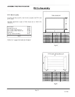
Fig. 7.3
RU 3s Section diagram showing mastic placement
RU 3s
max. kW
oil kg/h
Nat. gas
m³/h
10
1050
96
122
11
1160
106
135
12
1280
117
149
13
1395
128
162
14
1400
128
165
Type and
no. of sections
Output and fuel consumption
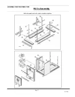
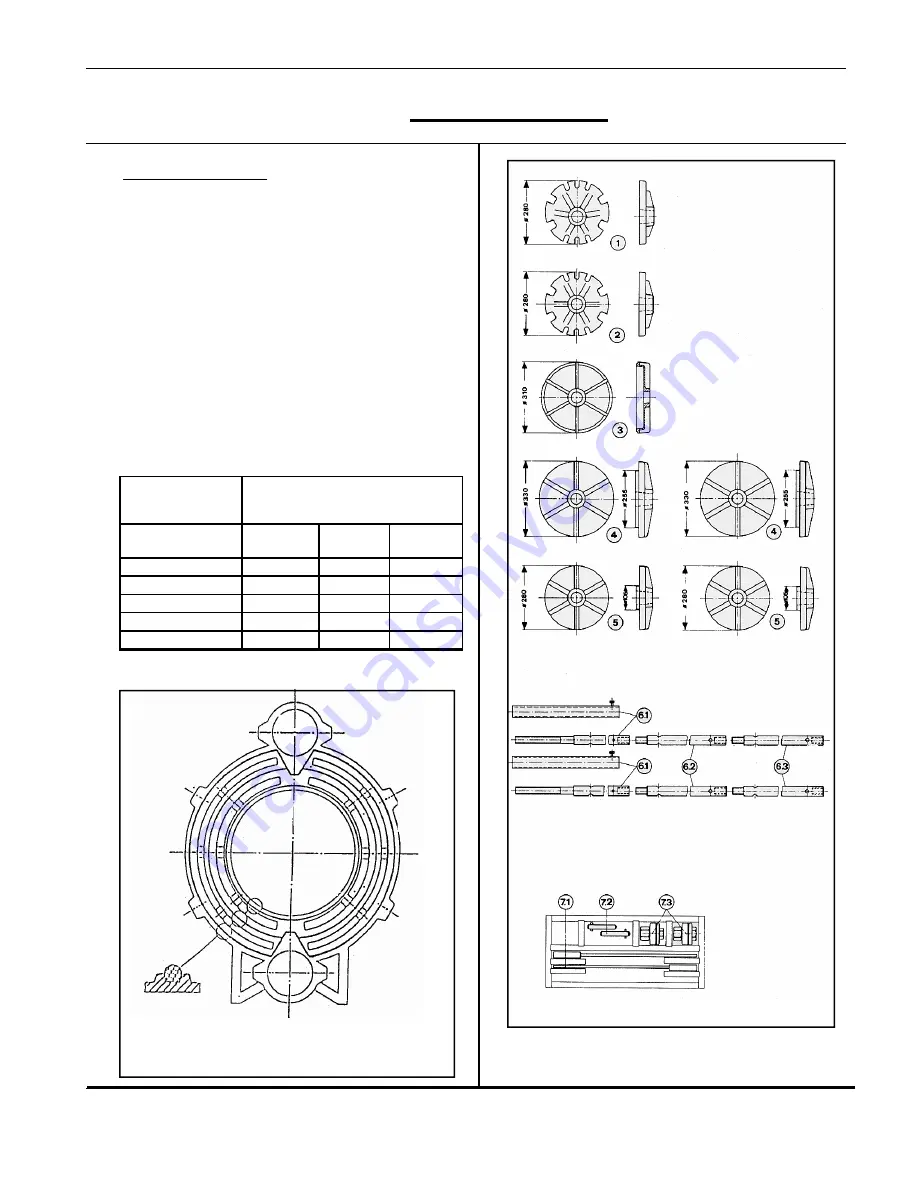
Fig. 6.3
Pulling-up kit (Fig. 8.3)
Key:
1.
Pulling-up flange at the top rear section
2. Pulling-up
flange
at
the bottom rear section
3. Nipple
flange
4.
Pulling-up flange for intermediate setions
5.
Pulling-up flange for front section
6.1 Basic
bar
6.2 Extension
bar
6.3
End piece bar
7.1 Free-running
ratchet
spanner
7.2 Stop
pins
7.3
Starting nut with thrust bearing
Fig.8.3
ASSEMBLY
INSTRUCTIONS
FOR:
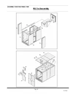
RU 3s Assembly


