K4
Changes in models reserved.
Dimensions not binding!
21
Boiler Design
General Information
17
1
condensing exchanger
2
input of return water to the exchanger
3
pump
4
input of return water to the pump
5
heating system (radiators)
6
output of hot water from the exchanger
7
input of hot water to the radiators
8
filling valve
9
pressure relief valve
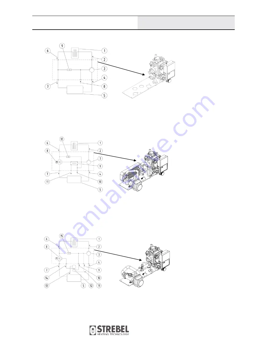
Fig. №. 5
VIADRUS K4G1HXXXX with only water heating for the system
(hydraulic diagram of the version and the sketch of the hydro-block)
1
condensing exchanger
2
input of return water to the exchanger
3
pump
4
input of return water to the pump
5
heating system (radiators)
6
output of hot water from the exchanger
7
input of hot water to the radiators
8
three-way valve
9
flow type water heater
10
input of water to the flow type water heater
11
output of water from the flow type water heater
12
pressure relief valve
Fig. №. 6
VIADRUS K4G2HXXXX with a flow type heater
(hydraulic diagram of the version and the sketch of the hydro-block)
1
condensing exchanger
2
input of return water to the exchanger
3
pump
4
input of return water to the pump
5
heating system (radiators)
6
output of hot water from the exchanger
7
input of hot water to the radiators
8
three-way valve
9
filling valve
10
output of hot water from the heater
11
refilling of water to the system
12
reservoir type water heater
13
relief valve of the heater
14
input of water to the heater
15
pressure relief valve
Fig. №. 7
VIADRUS K4G3HXXXX the boiler version
(hydraulic diagram of the version and the sketch of the hydro-block)
K4G1HXXXX with only water heating for the system
K4G2HXXXX with a flow type heater
K4G2HXXXX with a flow type heater


