SYSTEM PUMP
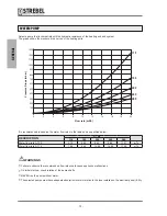
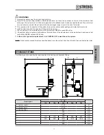
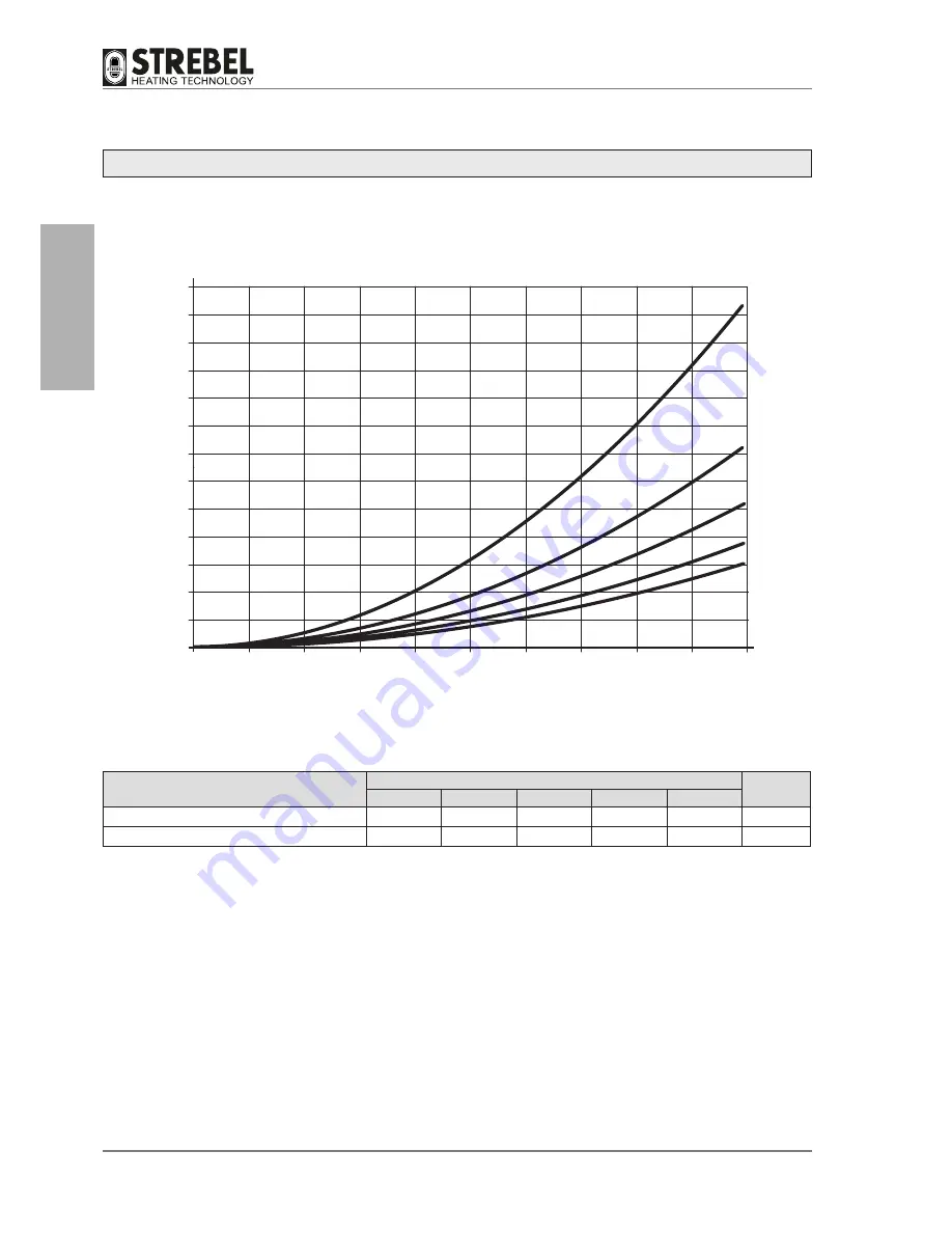
Select a pump that is compatible with the hydraulic resistance of the heating unit and system.
The graph shows the pressure drop curves of the heating units.
It is recommended to observe the water flow rates in the table and as specified below.
b
WARNINGS
•
Failure to observe the recommended flow rates could cause appliance malfunctions.
•
On initial start-up, check rotation of the pump shafts.
•
NEVER run the pump without water.
•
The selected pumps must have adequate absorption levels in relation to the fuse installed on the electrical panel (6.3A).
0
Pressure Drops (mbar)
Flow rate (m3/h)
1000
1100
1200
1300
900
800
700
600
500
400
300
200
100
0
2
4
6
8
10
12
14
16
18
20
115
150
200
240
280
DESCRIPTION
S - AF
115
150
200
240
280
Water flow rate ΔT 20
4.72
6.30
8.42
9.88
11.57
m
3
/h
Water flow rate ΔT 15
7.08
9.45
12.63
14.82
17.36
m
3
/h
- 10
-
GENERAL
- 10
-
Summary of Contents for S-AF
Page 63: ...NOTES 63 ...


