101
15.4 Cascade Error handling
15.4.1 C
ASCADE
F
ROST PROTECTION
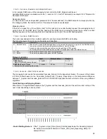
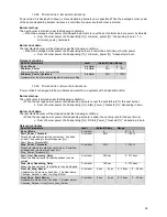
Frost protection on a cascade is active on two levels
1. Frost protection for burner cascade
The ‘frost protection’ function for a burner cascade is related to the boiler sensor temperatures.
When the supply / return temperatures of the managing boiler are below:
Cascade_Frost_ Protection:
The cascade CH/system pump and the general pump of the managing
boiler start running.
Cascade_Frost_Protection
+5 °C (41 °F)
Cascade heat demand is activated; the general pumps of all the cascaded
boilers will be started.
Demand with setpoint Cascade_Frost_Protection allows the boilers to
start burning until the return temperature of the managing boiler is above
Cascade_Frost_Prot5 °C (41 °F).
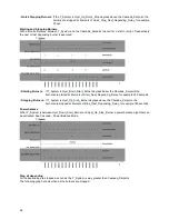
2. Frost protection on boiler
At last protection the controllers for the boilers can force themselves to burn.
If the boiler supply/return temperature drops below 5 °C (41 °F) the boiler starts at minimum power and continues
burning until the lowest of both supply and return temperatures are above 15 °C (59 °F).
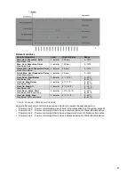
Specific Parameters
Level
(Default) Value
Range
Cascade frost protection
Temperature for frost protection
2: Installer 15 ºC (59 ºF)
10...30 ºC (50...86 ºF)
15.4.1 E
MERGENCY MODE
Open / Shorted boiler or system sensor
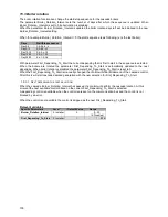
When the setting Emergency_Mode is enabled the control can go into emergency mode when the system sensor
status is open or shorted.
The managing boiler display may show that the system is in emergency mode.
In emergency mode the system setpoint is set to the Emergency_Setpoint (settable via installer menu) and all
cascaded boilers are allowed to start burning on this setpoint.
Loss of cascade communication
The burner controller of the managing boiler is aware of how many dependents should be present in the system.
The total number of boilers is set in parameter 147. When powering on the system the leading boiler has to detect
all depending boilers within 60 seconds.
When not all dependent boilers are detected the control will show the CC_Loss_Communication warning. When
the communication with any of the depending boilers is lost during operation, the control will show the
CC_Loss_Communication warning after 60 seconds, which is purely informative and will not block the control.
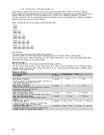
Specific Parameters
Level
(Default) Value
Range
Emergency_Mode
1: User
Yes
Yes/No
Emergency_Setpoint
2: Installer 70 ºC (158 ºF)
20 - 90 °C (68 - 94 °F)
15.4.2 M
ANAGING BOILER ERROR
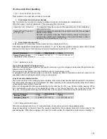
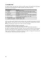
When the managing boiler is in error mode this boiler is not used anymore for the cascade system.
However depending on the error code, the pumps connected by the managing boiler still can be active for the
cascade system. When the managing unit is reset from lockout state, the cascade controllers are re-initialized.
Summary of Contents for S-CBX 105
Page 2: ......
Page 40: ...40 9 10 Flue Terminal Positioning ...
Page 42: ...42 9 11 1 FIGURE 12 LINE G ...
Page 55: ...55 11 5 Ladder Logic Diagram ...
Page 56: ...56 11 6 Electrical schematics ...
Page 57: ...57 ...
Page 137: ......

