102
16 SYSTEM TEST.
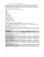
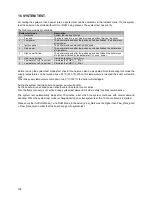
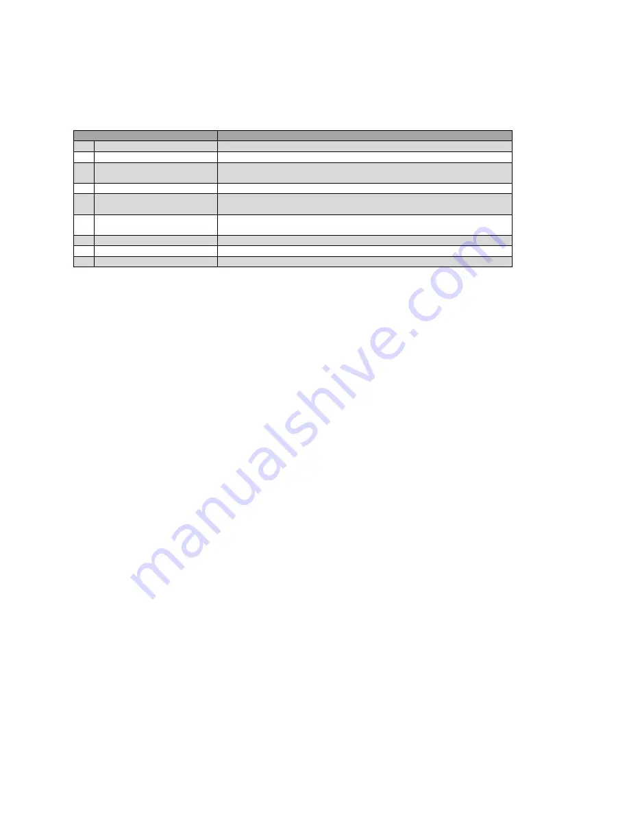
For testing the system at fixed power rates, a system test can be activated via the Installer menu. Via the system
test the boiler can be started without CH or DHW being present. The system test has priority.
The following modes are available:
System test mode
Description
0
Not active
System test mode not active
1
Fan only
The fan is forced to run at maximum speed without starting the boiler
2
Low power
The boiler starts and after the ignition period has finished the boiler stays
at low power
3
Ignition power
The boiler starts and stays at ignition power
4
High power
The boiler starts and after the ignition period has finished the boiler stays
at high power
5
High power limited
The boiler starts and after the ignition period has finished the boiler stays
at high power limited by the parameter
CH_ max_ power
6
High limit error test
Simulates the
Max_Temp_Error
7
Low water cut off 1 error test Simulates the
LWCO_1_ Error
8
Low water cut off 2 error test Simulates the
LWCO_2_ Error
Before running the system test modes first check if the heat can also be dissipated. Note that during this mode the
supply temperature can be raised above 95 ºC (203 ºF). When this temperature is reached the boiler will switch
OFF.
When the supply temperature cools down to 90 ºC (194 ºF) the boiler will start again.
During the system test the boiler and system pump will be ON.
As the boiler will run at fixed power rates there is no setpoint control active.
Also the flame recovery is not active during system test demand. All other safety functions remain active.
The system test automatically stops after 10 minutes, after which the system continues with normal demand
handling. When the system test mode is changed during an active system test, the 10-minute timer is restarted.
Please note that for DHW Mode_7 and DHW Mode_8 the Actual_Flow_Rate must be higher than Flow_Rate_Start
+ Flow_Rate_Hyst in order that the board can go into system test.
Summary of Contents for S-CBX 105
Page 2: ......
Page 40: ...40 9 10 Flue Terminal Positioning ...
Page 42: ...42 9 11 1 FIGURE 12 LINE G ...
Page 55: ...55 11 5 Ladder Logic Diagram ...
Page 56: ...56 11 6 Electrical schematics ...
Page 57: ...57 ...
Page 137: ......

