118
Insulation
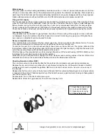
The insulation of the heat exchanger (located on the rear wall inside the heat exchanger and burner door) must
be inspected. If this insulation disc shows any signs of (water) damage or degradation it should be exchanged.
Also check if there are any indications in the burner room of a high condensate level (caused by a blocked
condensate trap) that might have wetted the rear wall insulation. When this has happened the rear wall insulation
should also be replaced.
Only use the insulation disk that is supplied by the boiler manufacturer.
The same procedure must be applied on the insulation and gaskets fitted on the burner door.
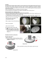
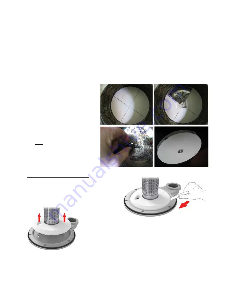
Rear wall insulation disk; changing procedure:
If the insulation disc has been degraded or damaged, it has to be replaced.
- Be sure the heat exchanger is cooled down, wait a few hours after burning. In this way, the protective film is not
sticking anymore on the rear side of this insulation disk.
- To prevent debris from falling in between the coils, place a sheet (e.g. paper) on the bottom, beneath the disk.
- Make the insulation wet, by spraying water over it. This in order to keep airborne dust to a minimum.
- With a knife, cut a cross in the insulation
disk, avoiding the central insert
(on the back, not visible)
- Make a square cut around the central insert
- Remove the segments
- Remove the central insert
The new disc has the clip on the back.
- Do
NOT
remove the film on the new disc
- With the central insert on the back, place
the new insulation disk by pushing it to
the rear of the wall. A "click" means the
fitting is ok.
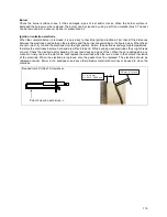
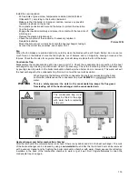
Replacement of burner door insulation.
Removal of the insulation:
- Remove electrode
- Remove the defective insulation by sliding under the
periphery of the insulation a thin tool to loosen the
insulation and remove it.
- Remove and clean the residues of the insulation and silicone glue.
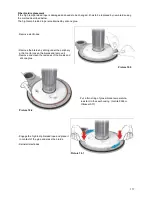
Picture 19.8
Picture 19.9
Picture 19.11
Picture 19.10
Picture 19.12
Picture 19.13
Summary of Contents for S-CBX 105
Page 2: ......
Page 40: ...40 9 10 Flue Terminal Positioning ...
Page 42: ...42 9 11 1 FIGURE 12 LINE G ...
Page 55: ...55 11 5 Ladder Logic Diagram ...
Page 56: ...56 11 6 Electrical schematics ...
Page 57: ...57 ...
Page 137: ......

